If you’re experiencing issues with your cleaning device, it’s essential to have a clear understanding of the internal mechanics. Each element, from the water intake to the spray nozzle, plays a vital role in ensuring smooth operation. Identifying the parts responsible for maintaining consistent water flow and pressure is crucial for effective troubleshooting and repair.
For a comprehensive analysis, begin by focusing on the inlet valves. These components regulate the water entering the system. Damaged or clogged valves can lead to inconsistent water flow, affecting overall performance. Regular inspection ensures these elements are functioning as intended, preventing unnecessary wear on other parts.
Next, inspect the component responsible for generating the force required for cleaning tasks. This element operates by converting mechanical energy into fluid pressure. If this unit is malfunctioning, it could cause a significant drop in cleaning efficiency. Look for any signs of leakage or unusual noises that may indicate a fault within the assembly.
To complete your evaluation, focus on the delivery system. This includes the hoses and the mechanisms controlling the distribution of water under high pressure. Any obstruction or weakness in these areas could result in a loss of pressure, which would negatively impact performance. Ensuring all connections are secure and that there are no cracks or leaks is key to maintaining optimal operation.
Key Components of a Cleaning Equipment Mechanism

To maintain efficient operation, it’s crucial to understand the key components of the cleaning unit’s mechanical system. Here’s a breakdown of the essential elements:
- Water Inlet Valve: Controls the flow of water into the system, ensuring proper pressure levels.
- High-Pressure Chamber: This section is where water is pressurized before being directed through the nozzle for cleaning tasks.
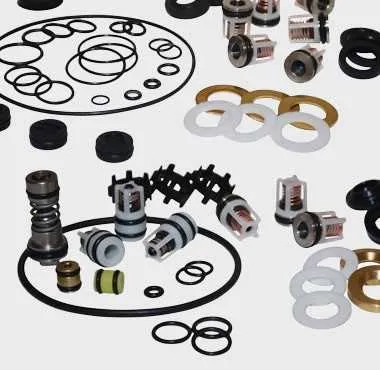
- Seal Assembly: These gaskets prevent leaks and ensure that all water remains contained within the system during operation.
- Crankcase: Houses the main driving mechanism and ensures smooth movement of internal parts, powered by the motor.
- Unloader Valve: Regulates water flow, especially when the device is idle, preventing unnecessary wear on the system.
- Discharge Valve: Controls the release of pressurized fluid, directing it towards the cleaning nozzle with the desired intensity.
- Connecting Rod: Transfers motion from the engine to the pump system, facilitating fluid movement under pressure.
Proper upkeep of these components ensures a longer lifespan for your equipment and consistent high-level performance. Regular inspection and timely replacement of worn parts is key to avoiding unexpected breakdowns.
Identifying Key Components in a High-Pressure Water System

Start by locating the water inlet valve. This is where the liquid enters the system, typically linked to a hose. Ensure this component is free from blockages to maintain optimal flow.
The impeller is a critical element that transfers energy to the fluid, increasing its velocity. Inspect the blades regularly for wear, as damaged blades can significantly reduce performance.
The discharge valve regulates the release of water. It must open and close properly without any sticking. Regularly clean it to avoid clogs that can hinder the flow of water to the nozzle.
Seals play an essential role in preventing leaks at various junctions. Over time, seals can degrade, causing leaks. Inspect and replace seals periodically to prevent water loss and system damage.
The unloader valve maintains consistent pressure by diverting excess fluid back to the intake when the trigger is not engaged. If it malfunctions, the system can experience pressure fluctuations.
Gaskets ensure tight seals between critical components. Examine them regularly for any cracks or deterioration that may compromise the system’s integrity.
Lastly, the piston drives the fluid through the system. If the piston becomes damaged, it can cause a loss of force and uneven water distribution. Ensure that it moves smoothly without any resistance.
How to Read and Understand the Pump Assembly Illustration
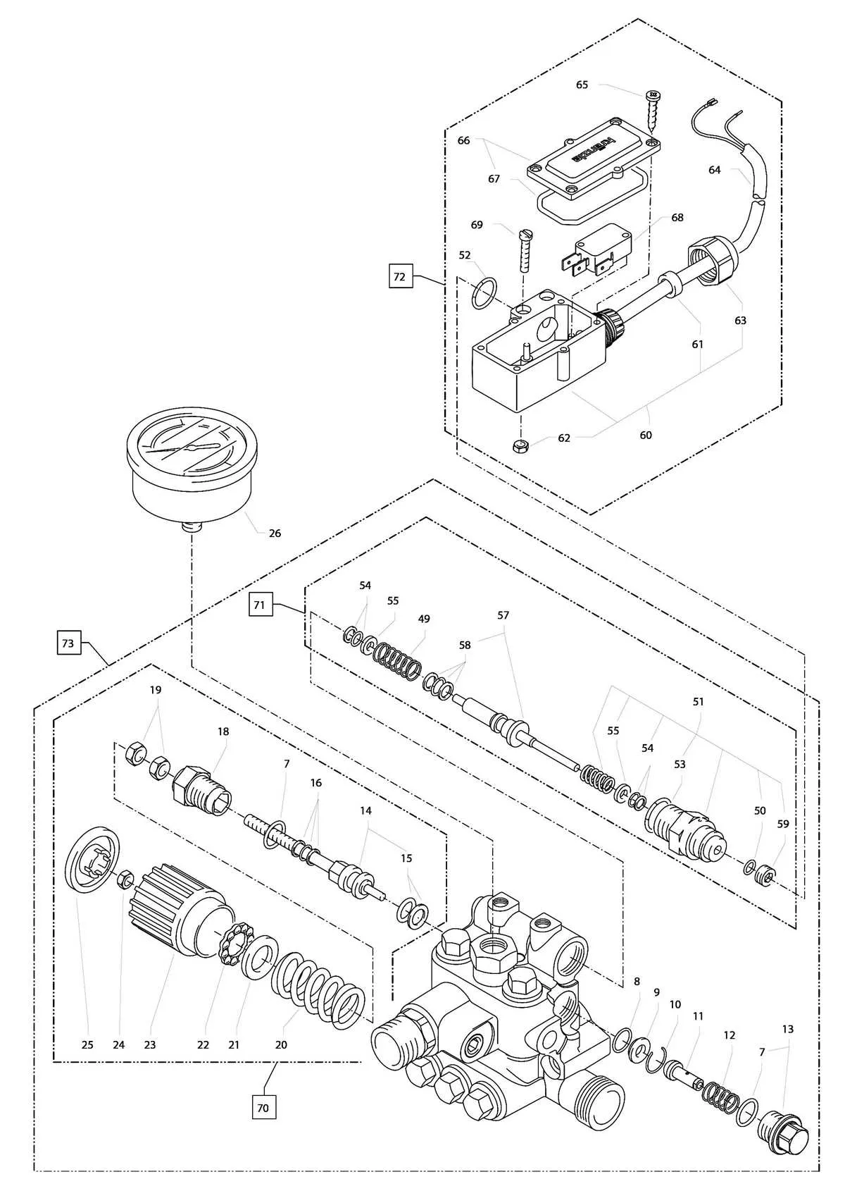
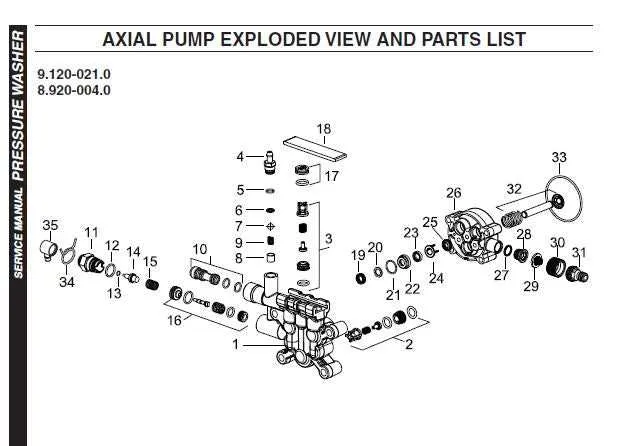
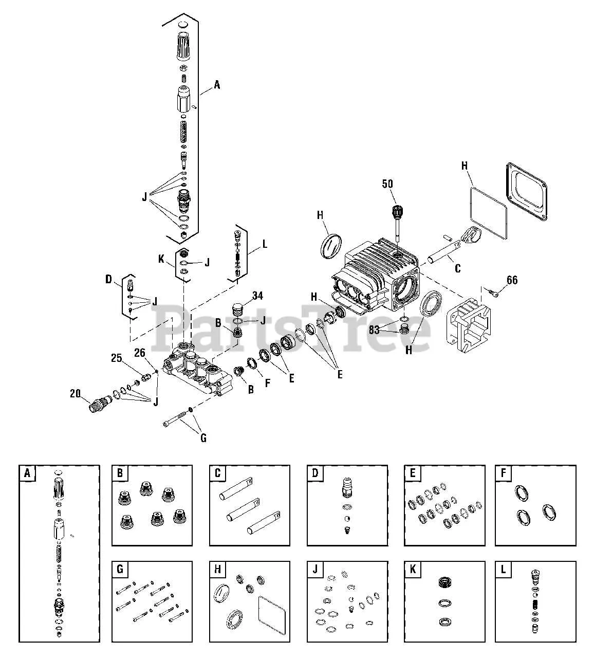
Start by identifying the key components marked on the schematic. Each symbol or label corresponds to a specific function or element within the device. Focus on the main components such as the inlet valve, cylinder, and connecting rods. These are often at the center of the graphic and determine the flow of fluid through the system.
Identify the Flow Path: Pay attention to arrows indicating the movement of the fluid. This will help you understand how water enters, is pressurized, and exits the system. The direction of flow often indicates the sequence of actions within the mechanism.
Examine the Functional Sections: The diagram typically separates the illustration into sections based on function. For example, one part may represent the intake and filtration process, while another part shows the compression or expulsion of water. Recognizing these divisions simplifies the overall understanding of the assembly.
Look for Annotations: Notes or labels provide crucial details about each part’s material, size, or specific function. If a component is adjustable or replaceable, this is often highlighted in the diagram. Pay close attention to these to determine maintenance needs.
Cross-Check with the Manual: For precise identification, compare the symbols with the parts list in the user guide. The manual typically explains the diagram in detail, giving you further insight into each component’s purpose and maintenance requirements.
Lastly, become familiar with common schematic conventions such as dashed lines for hidden or internal elements and solid lines for visible connections. Understanding these conventions will help you interpret any similar diagrams in the future.
Common Issues and Maintenance Tips for Pump Components

Regularly inspect the seals and O-rings for any signs of wear or cracking. If you notice leaks around these components, replace them immediately to avoid further damage.
Ensure the inlet valve is clear of debris to maintain proper water flow. Clogged valves can result in inefficient operation or complete failure, so cleaning or replacing the valve is critical for optimal functioning.
Lubricate the internal moving parts as per the manufacturer’s recommendations. Lack of lubrication can lead to excessive friction, causing overheating and potential breakdowns.
Examine the unloader valve periodically. If it sticks or malfunctions, it can lead to pressure inconsistencies. Test it regularly and replace if necessary to ensure steady operation.
Over time, the bearings can degrade, especially if exposed to water or harsh conditions. Regularly check for unusual noise or resistance during operation. If detected, lubricate or replace the bearings to maintain smooth motion.
Check the drive system for misalignment or wear. If you notice any irregularities in the motion or hear grinding sounds, it’s crucial to adjust or replace components to prevent further damage to the mechanism.
Ensure the check valve is functioning correctly. A malfunctioning check valve can cause backflow, which may damage the internal components. Test it regularly and replace if needed.
Inspect the high-pressure hose for signs of kinks, cuts, or abrasions. Damaged hoses can cause loss of pressure and are a safety hazard. Replace any worn hoses immediately.
Flush the internal system with clean water after each use to prevent buildup of sediment or mineral deposits that can clog or damage components.