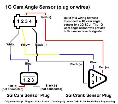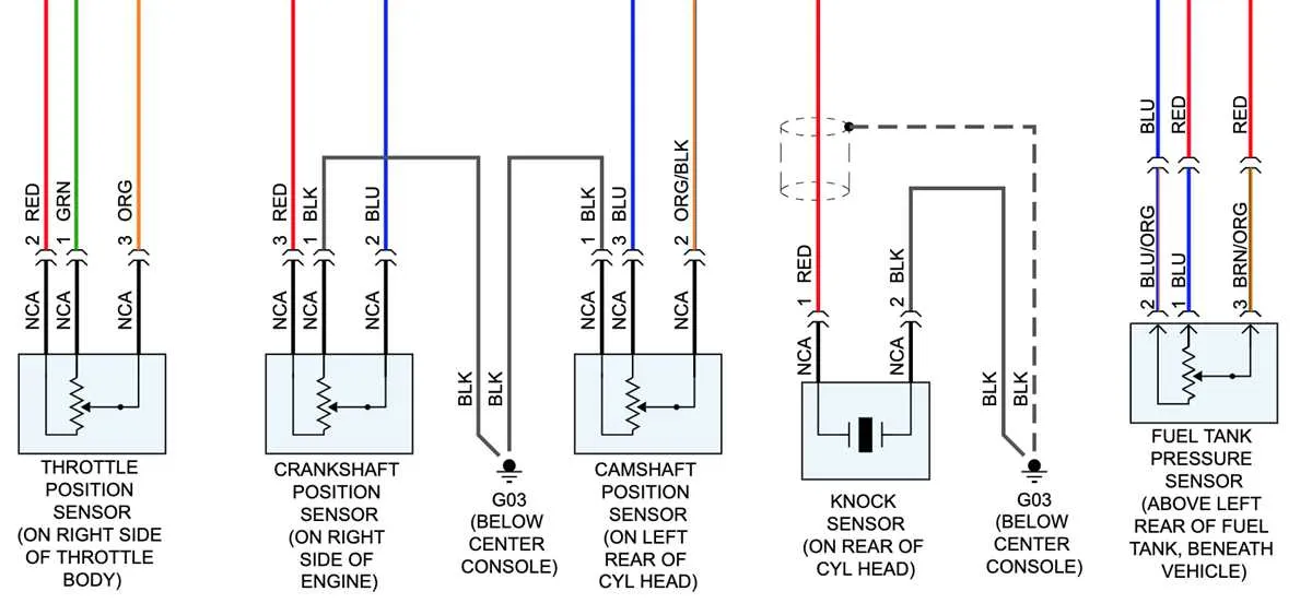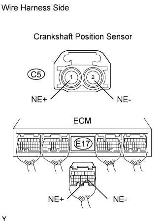
For accurate engine performance monitoring, it’s crucial to correctly configure the connection between the engine control unit (ECU) and the positioning device. Ensure proper alignment of the two-terminal component with the corresponding input on the ECU. This ensures seamless communication between the two elements, enabling precise readings for timing adjustments and diagnostics.
When setting up the circuit, focus on the polarity of connections. One terminal typically links to the ECU’s ground, while the second connects to the power supply. Double-check that the connection is secure to avoid intermittent signals or erratic engine behavior.
For optimal results, it’s essential to use high-quality connectors and avoid long cables, as they can introduce noise into the system. Keep the connecting path as short and direct as possible to maintain signal integrity, especially in high-vibration environments.
Important tips: Pay close attention to the physical location of the component on the engine. It must be positioned precisely to align with the rotating part it monitors. Incorrect positioning can lead to inaccurate readings and poor engine performance.
Regular maintenance and periodic inspections will help identify any degradation of the connection or component, ensuring the system operates at peak efficiency throughout the vehicle’s lifespan.
2-Wire Engine Position Detection Setup

For proper connection of a 2-pin engine position detection device, follow these steps:
Pin 1: Connect to the vehicle’s main power supply. Typically, this is a 5V or 12V input depending on the system voltage. Ensure the voltage level matches the device’s requirements to avoid damage.
Pin 2: Link to the ECU input or the signal processing unit. This output carries the pulses corresponding to the engine’s rotational position, which the control system interprets. Proper grounding of the ECU is essential for accurate signal reception.
Make sure to use high-quality connectors and ensure tight, corrosion-resistant contacts. Avoid sharp bends in the cable, as this could cause intermittent failures or data loss. Keep the connection as short as possible to reduce signal degradation.
For accurate readings, install the device close to the engine’s rotating part, ensuring it is aligned properly according to manufacturer instructions.
Identifying Pinout and Wire Colors for 2 Wire Crank Sensors
To correctly identify the pinout for a two-conductor ignition position unit, start by locating the connector. The first terminal typically serves as the ground, usually coded with a black or brown hue. The second terminal is usually the signal output and is often marked with a green or yellow color. However, it’s important to check the specific vehicle’s manual or service guide, as color schemes may vary slightly across manufacturers and models.
For vehicles equipped with a two-wire unit, the power side (signal) will often connect to the ECU or control module, where its output is processed. The ground terminal connects to the vehicle’s frame or direct ground point. This information is crucial for ensuring accurate signal transmission, as improper connections can lead to system errors or incorrect readings.
Before making any replacements or modifications, verify the component’s pin configuration using a multimeter to ensure proper electrical contact and functionality. It’s also recommended to trace the cable to the ECU if uncertain about the correct identification of each pinout.
How to Connect the 2-Wire Engine Position Module to the ECU

To establish a connection between the engine position module and the ECU, locate the two terminals on the module: one for signal output and one for ground. Begin by connecting the signal terminal directly to the ECU’s corresponding input pin, typically labeled for RPM or timing signals. Ensure that the connection is solid and free from any corrosion or damage that could cause electrical interference.
Next, link the ground terminal of the engine position module to a clean chassis ground or the ECU’s designated ground pin. This ensures proper voltage reference for accurate signal processing. It’s crucial to verify that the ground is securely connected to avoid false readings or instability in engine performance.
Check the pinout of the ECU to ensure compatibility with the engine position module’s signal specifications, which may vary based on the vehicle model. Use a multimeter to verify proper voltage levels after making connections, ensuring that the signal pulse is being transmitted correctly to the ECU. If necessary, consult the vehicle’s service manual for exact details on pin assignments.
Finally, test the system by starting the engine and monitoring the ECU’s response. Look for any irregularities or error codes that might suggest an issue with the installation. A properly connected module will allow the ECU to accurately track engine speed and timing, improving overall engine performance.
Troubleshooting Common Electrical Issues with 2-Wire Engine Timing Components
If the engine fails to start or misfires, the first thing to check is the connection between the component and the ECU. Ensure that both terminals are securely fastened. Loose or corroded connections can lead to inconsistent data being sent to the control unit.
- Check continuity: Use a multimeter to verify that the signal and ground paths are intact. Breaks in either path can cause intermittent or total failure of the signal transmission.
- Inspect for short circuits: A short between the signal and ground conductors can cause the component to send incorrect readings, preventing proper engine operation.
- Verify correct placement: Ensure that the component is properly aligned with the rotating element, and no foreign objects are obstructing it. Misalignment can lead to inaccurate data output.
Another common issue is damaged insulation. Check for any cuts or abrasions along the insulation, which can lead to grounding or interference, corrupting the signal.
- Visual inspection: Look for frays or exposed sections of the conductors. Replace any damaged sections immediately to prevent further issues.
- Test under load: With the engine running, test the component’s output. A drop in voltage or signal fluctuation can indicate a fault in the cable or the component itself.
Temperature fluctuations can also affect the performance of the system. Ensure that the component and connections are not exposed to excessive heat, which can degrade the performance of the electrical parts.
- Check insulation rating: Verify that all parts are rated for the temperatures they may encounter. Overheated components are prone to failure.
- Thermal expansion: Confirm that connections remain tight even after the engine reaches operating temperature, as metal parts can expand and cause intermittent issues.
Finally, always verify the proper voltage and signal type as specified by the manufacturer. Using incorrect voltage can lead to malfunction or complete failure of the part.