For precise engine functionality and optimal fuel delivery, it’s crucial to understand the layout and connections of the fuel metering system. If you’re experiencing performance issues like poor idling or difficulty starting, a thorough inspection of the fuel system components can often identify the root cause. Identifying where the air and fuel mix, and how the components interact with each other, will help you resolve most common issues.
Focus on the essential connections: The fuel delivery unit consists of several parts that directly affect the engine’s fuel mixture. Pay special attention to the alignment of the intake valve, throttle linkage, and airflow channels. Misalignment or clogging of these parts can lead to uneven fuel supply, resulting in stalling or lack of power during operation.
Additionally, ensure all sealing gaskets are intact to prevent any air leaks, which could compromise the air-fuel ratio and negatively affect engine performance. Understanding how these components work in unison can save both time and money when troubleshooting engine performance issues.
Fuel System Assembly Overview

The key to proper operation lies in the correct installation and maintenance of the fuel delivery system. Begin by ensuring all parts are in their correct positions and aligned according to the specifications. The main components involved include the fuel pump, intake manifold, and throttle body, each working in unison to regulate the flow of the mixture to the engine.
Fuel Delivery Unit: This is responsible for delivering the air-fuel mixture to the engine. Ensure that the diaphragm is intact and free from any cracks or signs of wear. Any damage here can result in inconsistent fuel flow, leading to starting or performance issues.
Mixture Adjustment: Proper tuning of the mixture screws controls the engine’s fuel efficiency and idle stability. Make sure to adjust the low and high-speed needles correctly, based on manufacturer guidelines. Adjusting them too far in either direction can result in excessive fuel consumption or poor engine performance.
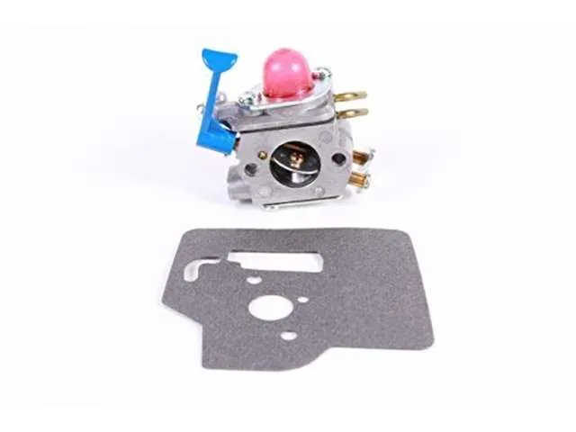
Gasket Inspection: Always check the gaskets for any signs of leaks or wear. Even small cracks can cause air or fuel leaks, which will disrupt the engine’s performance. Ensure they are properly sealed before reassembly.
Fuel Filter: Inspect the fuel filter regularly. A clogged filter restricts fuel flow, causing the engine to starve or run erratically. Replacing the filter at least once a year is recommended for optimal performance.
Component Placement: Be mindful of component orientation, particularly the fuel line connections. Correct placement of fuel lines and connectors ensures an uninterrupted flow, preventing the risk of fuel leakage or system failure.
Assembly Check: After reassembling the fuel system, double-check all fasteners and connections to ensure they are secure. Loose or improperly fastened parts can lead to performance issues or complete system failure.
Disassembling the Carburetor for Inspection
To properly inspect the fuel system’s components, follow these steps for disassembly:
- Ensure the engine is completely cooled and all fuel is drained to avoid leaks.
- Disconnect the spark plug wire for safety.
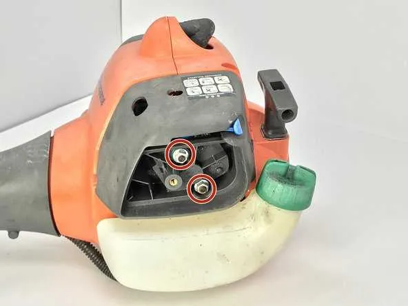
- Remove the air filter housing and any connecting components to access the carburetor.
- Loosen the screws securing the carburetor to the intake manifold.
- Carefully detach the fuel lines from the carburetor. Use caution to prevent damage to the hoses.
- Remove the mounting bolts or screws, and lift the assembly free from the engine block.
Once the unit is removed, follow these steps to inspect:
- Examine the gasket for any wear or signs of fuel leakage.
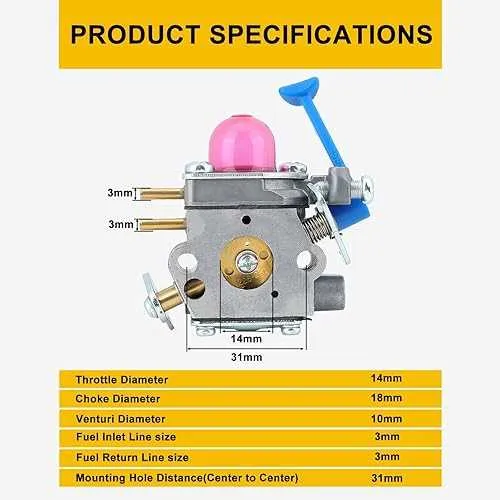
- Inspect the fuel inlet and outlet ports for blockages or debris.
- Check the needle valve and seat for any buildup that could obstruct fuel flow.
- Verify the condition of the diaphragm and any springs for flexibility and strength.
- Clean each component with a non-abrasive solvent to remove dirt or carbon buildup.
If any parts appear damaged or excessively worn, they should be replaced before reassembling.
Identifying Key Components in the Carburetor Assembly

The fuel system of small engines requires careful attention to its primary elements. In this context, focus on the following components to ensure proper functionality and troubleshooting:
The fuel metering valve regulates the flow of fuel into the engine based on the throttle position. It’s crucial for maintaining the proper air-fuel ratio. Check for any wear or clogging in the needle or seat, as this can lead to improper fuel delivery.
The air intake and choke mechanism controls the airflow into the combustion chamber. When examining this part, make sure the choke lever operates smoothly and isn’t obstructed, as a malfunction can cause starting issues or poor engine performance.
The idle screw allows for fine-tuning the engine’s idle speed. Adjust it carefully to avoid stalling or erratic idling behavior. Over-tightening or loosening can lead to significant engine performance problems.
The diaphragm pump plays a vital role in regulating fuel pressure. Inspect the diaphragm for cracks or damage, which can lead to inconsistent fuel delivery and poor engine performance.
The jetting system consists of several orifices that control the fuel-air mixture at different engine loads. If any of these jets are clogged or corroded, they can affect fuel delivery at high or low speeds. Regular cleaning and inspection are essential for maintaining optimal engine performance.
The venting system ensures proper pressure regulation within the fuel system. Make sure the vent lines are free from blockages and that the pressure valve functions correctly. A malfunction here can lead to fuel leakage or inconsistent engine power.
Reassembling and Adjusting the Carburetor for Optimal Performance
Start by securing the components tightly in place, ensuring that the gasket is correctly seated to prevent any air leaks. Position the throttle body and air filter assembly accurately to avoid misalignment, which can result in inefficient fuel delivery. Before proceeding with reassembly, inspect all parts for wear or damage, replacing any faulty components to ensure a smooth operation.
When reattaching the fuel line, make sure it is securely connected, without any twists or kinks, as this can restrict fuel flow. Reconnect the choke lever and ensure it moves freely without obstruction. Verify the throttle linkage and governor are functioning properly, adjusting them if necessary to maintain proper engine speed regulation.
Once reassembled, start with idle speed adjustments. Turn the idle screw clockwise until it lightly seats, then back it off about 1–1.5 turns to find the baseline idle speed. Fine-tune by adjusting the air/fuel mixture screw to achieve a stable idle. If the engine surges or stalls, the mixture may be too rich or too lean, requiring further fine-tuning.
Next, check the high and low-speed jet settings. The low-speed jet should provide smooth acceleration, while the high-speed jet ensures maximum performance at full throttle. Adjust these settings incrementally and test the engine’s response at different throttle positions. Always perform these adjustments in small increments to avoid over-adjusting, which can lead to poor performance or engine damage.
After adjustments, test the machine under load to ensure proper operation. Pay attention to engine response, fuel consumption, and exhaust emissions. If the engine hesitates, backfire, or fails to reach full speed, further tuning may be necessary, particularly to the high-speed mixture screw or idle speed settings.