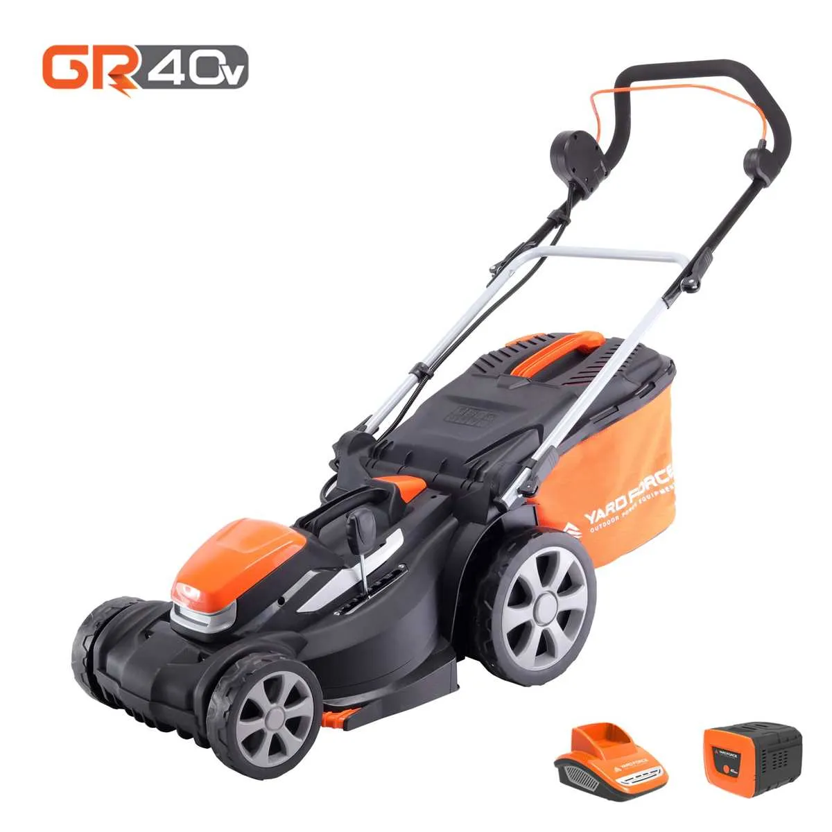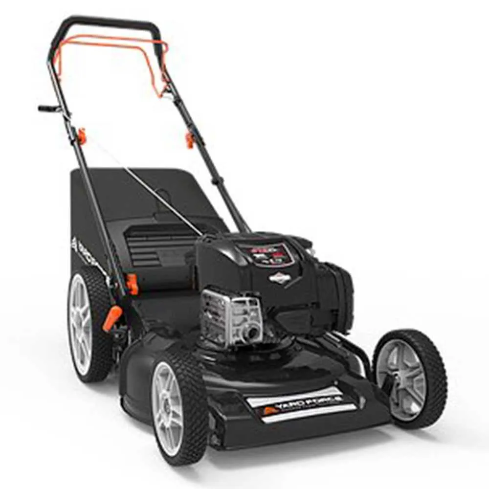
Start by carefully examining the various elements of your grass trimming machine to ensure optimal performance. Each component plays a vital role in how efficiently the device operates, and knowing their exact placement and function will simplify any repair or maintenance tasks. Focus first on the engine assembly, as it powers the entire unit. Check the spark plug, air filter, and fuel system to avoid starting issues and ensure smooth operation.
Next, turn attention to the cutting mechanism. The rotary blades should be sharp and well-balanced, with no signs of wear or damage. Make sure the blade attachment is secure, as any loose fastenings can reduce cutting effectiveness. The height adjustment mechanism is equally important for controlling the cutting length, which should be checked regularly for ease of adjustment and secure locking.
Don’t overlook the chassis and wheels. The frame supports all components, and the wheels are essential for smooth movement across various terrains. If you notice the device is hard to push or steer, inspect the wheel axles and the wheel height adjustment system for any malfunctions.
Lastly, review the electrical or battery system if your equipment includes such features. Ensure the battery is charged and the electrical connections are clean and free from corrosion. A thorough understanding of these parts can help prevent major issues before they arise, saving both time and money in repairs.
Understanding the Key Components of Your Garden Tool

When performing maintenance on your garden machine, it’s essential to familiarize yourself with its main components to ensure proper function and longevity. Start by identifying the engine, the central piece responsible for power generation. The spark plug plays a crucial role in igniting the engine, while the fuel tank holds the necessary gasoline to keep the tool running.
Next, examine the cutting mechanism. The blade assembly, including the spindle and blade drive, ensures smooth operation and effective cutting. The deck housing serves as the protective casing that holds the blade in place while also providing structural support. Additionally, check the air filter, which prevents dirt and debris from entering the engine, thereby improving performance and extending its life.
The handlebar and control system, including throttle and brake levers, allow you to control the movement and operation of the device. Ensure that all links are free from rust and wear, as damaged controls can affect handling and safety. Regularly inspect the wheels to ensure they are properly aligned and capable of supporting the machine’s weight while moving over varying terrains.
Lastly, ensure the battery (if present) is in good condition. It powers any electric start mechanism or auxiliary features, such as lights or automated adjustments. Always consult the specific model guide for detailed maintenance instructions to avoid unnecessary damage or malfunction.
How to Identify Key Components in a Lawn Equipment Blueprint
Start by locating the main drive mechanism, usually situated near the center of the schematic. It typically consists of a motor, belt, and pulleys that power the entire machine. Check for any labels that denote these elements to avoid confusion with other systems.
Next, focus on the cutting assembly. This will be prominently displayed and is often represented by blades, spindles, and a housing unit. Look for the connections between these components, which are essential for effective operation.
The fuel or energy source is another critical area. If the equipment runs on gasoline or electricity, identify the fuel tank, battery, or wire connections. These are vital for powering the machinery and must be clearly marked.
Examine the control interface carefully. This will usually include switches, levers, and a throttle mechanism. Understanding the exact placement and function of each will help in troubleshooting and maintenance.
Finally, locate the chassis and wheel system. These provide mobility and balance, often depicted with axle, bearings, and suspension components. Pay attention to their alignment and interaction with the rest of the assembly.
Step-by-Step Guide to Replacing Lawn Care Machine Components
Begin by ensuring the engine is completely off and cool. Disconnect the spark plug to prevent accidental starts during the process.
- Inspect the Manual: Review the machine’s manual for specific instructions and safety guidelines before beginning the replacement process.
- Prepare Tools: Gather necessary tools, including wrenches, screwdrivers, and any specialized equipment listed in the manual.
- Remove the Old Element: Identify the defective part by visually inspecting the device. For worn-out blades, nuts, or handles, use appropriate tools to remove them.
- Clean the Area: Before inserting new components, clean debris, dirt, and grass buildup around the area to ensure a proper fit.
- Install the New Piece: Align the replacement part with the corresponding connectors and secure it tightly to avoid future malfunctions. Make sure to tighten screws, bolts, or pins as required.
- Test the Assembly: After installation, reconnect the spark plug and perform a short test run. Verify that the new element is functioning as expected.
Follow these steps carefully to maintain the efficiency and safety of your outdoor equipment.
Troubleshooting Common Issues with Lawn Equipment Components Using Visual Guides
If your grass cutter is struggling to operate efficiently, the first step is to consult the visual breakdown of the internal elements. Identify any components that appear out of alignment or damaged. A frequent issue involves the engine not starting, which could be traced to a faulty ignition system or fuel flow obstruction. Examine the fuel lines for cracks or blockages using a visual aid to locate leaks.
Another common malfunction occurs when the device starts but loses power quickly. This can often be attributed to clogged air filters or obstructed blades. A detailed schematic will guide you to the filter section, which can be cleaned or replaced easily. Ensure that the cutting mechanism is not stuck due to debris buildup or worn-out parts, as this may reduce its efficiency.
Check the wheel assembly for irregular wear, which can cause uneven cutting. A closer inspection of the axles and wheel bearings can identify the source of a wobble or dragging motion. Use the visual representation to verify the correct position of each wheel, as improper alignment can affect the overall performance.
If your equipment emits excessive noise or vibrations, inspect the internal engine components like the crankshaft and connecting rods. The visual guide should highlight where wear might have occurred, such as on the blade mount or the belt system. Tightening loose bolts or replacing worn-out parts can prevent further damage and improve operation.
Lastly, if the device stalls or cuts out unexpectedly, it may be an issue with the electrical connections or the control switch. Use the diagram to trace wires and connectors, ensuring there are no frayed connections or dirt obstructing the contacts.