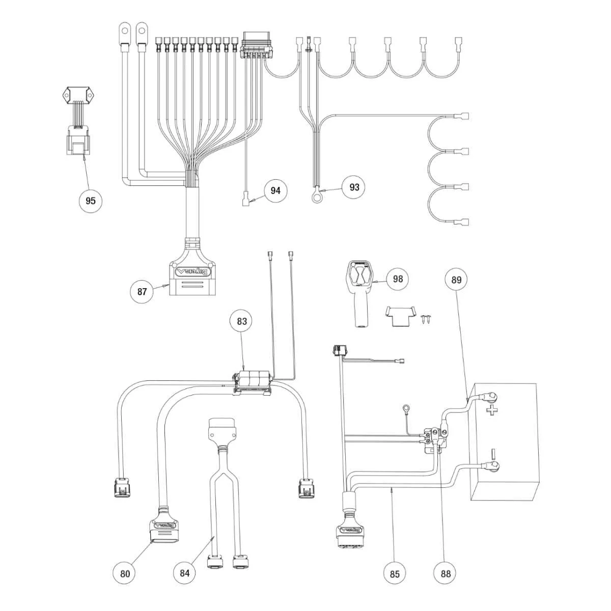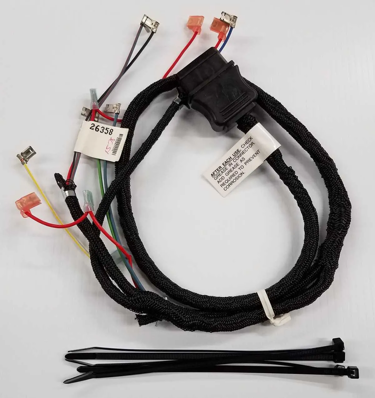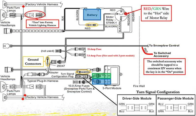
If you need to connect the electrical components of your snow removal equipment, start by carefully following a clear connection map that outlines each part of the system. This ensures proper functionality, preventing common issues like power failure or erratic performance during operation.
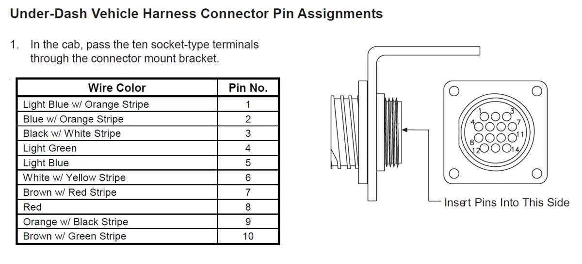
To begin, identify the main power feed from the vehicle’s battery. Make sure the connection is secure and well-insulated, as any loose wires can lead to intermittent issues or electrical shorts. Next, connect the control unit, which is responsible for managing the plow’s movements. Pay close attention to the wire colors and pinouts, as these must match the unit’s specifications to avoid malfunctions.
Ensure that all ground connections are solid. Poor grounding is one of the most frequent causes of electrical failure in snow removal systems. Test the ground points to verify they are free from corrosion, and clean them if necessary. Secure any exposed wires with appropriate connectors and weatherproof materials to protect against harsh conditions.
Lastly, don’t forget to verify the functionality of each component after installation. Testing all connections helps ensure the system operates correctly and safely. Refer to the manufacturer’s manual for troubleshooting tips and additional guidance on any model-specific nuances.
Installation Instructions for Snow Removal System Electrical Setup
To ensure correct installation and functionality of the electrical components for the snow removal setup, follow these precise steps:
- Connect the power cable to the battery terminal. Ensure the connection is tight and secure to prevent power loss.
- Route the main control unit cable through the vehicle’s interior, securing it along existing wire channels to avoid damage.
- Use a fuse box with a rating matching the power requirements of the system, placing it in an accessible location for future maintenance.
- Mount the control switch on the dashboard or other accessible areas, ensuring it is firmly attached and within easy reach of the operator.
- For lights and other external components, run the auxiliary wiring to the front section of the vehicle, taking care to prevent exposure to moving parts.
- Test the system by activating the controls. Verify all connections are secure and there are no exposed wires that could cause shorts or malfunctions.
It is important to check for any loose connections or improperly routed cables that may interfere with the operation of the snow removal equipment. Any issues should be addressed immediately to avoid malfunctioning during use.
How to Identify Components in a Snowplow Electrical Setup

Start by locating the main control unit, usually mounted on the vehicle’s dashboard. This unit has color-coded connectors that correspond to specific functions such as the lifting, lowering, or angling of the blade. Pay attention to the wiring that leads to the motor, as it will often have thicker insulation and heavier gauge wires for power delivery.
The next component to identify is the relay box. This piece is crucial for regulating the electrical current between the control switch and the motor. The relays inside typically have small metal pins, and the position of these relays in the box can be cross-checked with the manufacturer’s guide to ensure proper connection.
For precise functionality, focus on the switches and their corresponding wires. Each switch controls a specific motorized action, and each wire is insulated with distinct colors to prevent confusion. Test the switches by activating them and ensuring each action is synchronized with the correct wire.
Lastly, inspect the connectors at both ends of the cable run. These connectors are designed for quick installation and removal and may be marked with manufacturer-specific labels. Ensure that each plug is securely seated and locked in place, as loose connections can lead to intermittent electrical failures.
Step-by-Step Guide to Installing a Snow Removal Vehicle Electrical System

Begin by disconnecting the vehicle’s battery to prevent accidental short circuits. Locate the main power supply cable and ensure it has enough length to reach the designated areas. Mount the controller unit inside the cabin, choosing a position within easy reach but away from moisture or heat sources.
Next, connect the power cable from the vehicle’s battery to the central terminal block. Secure it tightly with a wrench to avoid any loose connections. Attach the secondary cables to the corresponding terminals, making sure to follow the correct polarity indicated in the user manual.
Route the wires along the chassis, avoiding sharp edges that could damage the insulation. Use zip ties or clips to secure them at regular intervals, ensuring they don’t interfere with moving parts. If the vehicle is equipped with a snow removal attachment, make sure to route the necessary control cables to the front of the vehicle, aligning them with the mounting brackets.
Once the cables are in place, test the connections by temporarily reconnecting the vehicle battery. Activate the control unit and verify that the electrical components are functioning correctly. Check for any loose connections or signs of overheating before securing everything with electrical tape or heat-shrink tubing for added protection.
Finally, reassemble any parts that were removed during the installation process. Perform a thorough inspection to ensure that all components are securely fastened and that no wires are exposed to potential damage. Conduct a final test to ensure the system operates smoothly under all conditions.
Troubleshooting Common Issues with Snow Removal Vehicle Electrical Connections

If the vehicle is not receiving power or the attachments are not functioning, begin by inspecting the primary power connections for corrosion or loose terminals. Ensure that all connectors are fully engaged and locked in place, as improper contact can lead to intermittent failures.
Check for continuity in the cables using a multimeter. If there is no power or irregular operation, this could point to a broken or frayed wire along the system. Pay special attention to any section exposed to movement or friction, as these are prone to wear.
Confirm that all fuses are intact and properly rated for the current draw of the system. A blown fuse might indicate an overcurrent situation, which can be triggered by poor wiring or short circuits. Replace any blown fuses with the correct type and rating to prevent further damage.
If the control module is unresponsive, reset it and verify all connections to the module are tight. Sometimes, loose or dirty connectors can cause malfunctioning by preventing proper data transmission.
For systems involving solenoids or relays, test these components for correct operation. A faulty relay or stuck solenoid can stop electrical signals from reaching the intended location, leading to non-functioning parts.
Lastly, inspect grounding points to ensure there is no oxidation or paint build-up interfering with proper electrical flow. A poor ground connection can cause erratic behavior or complete failure of the system, particularly in vehicles exposed to harsh weather conditions.