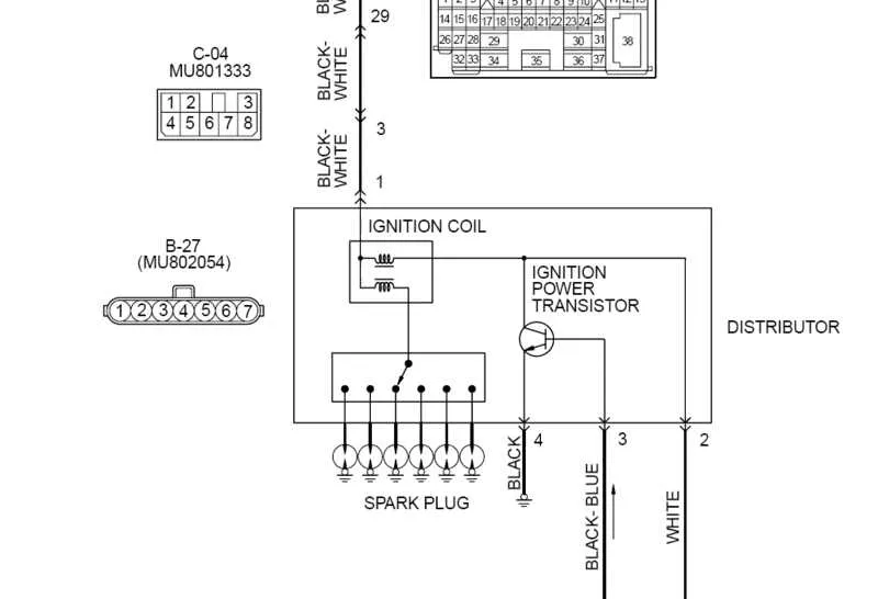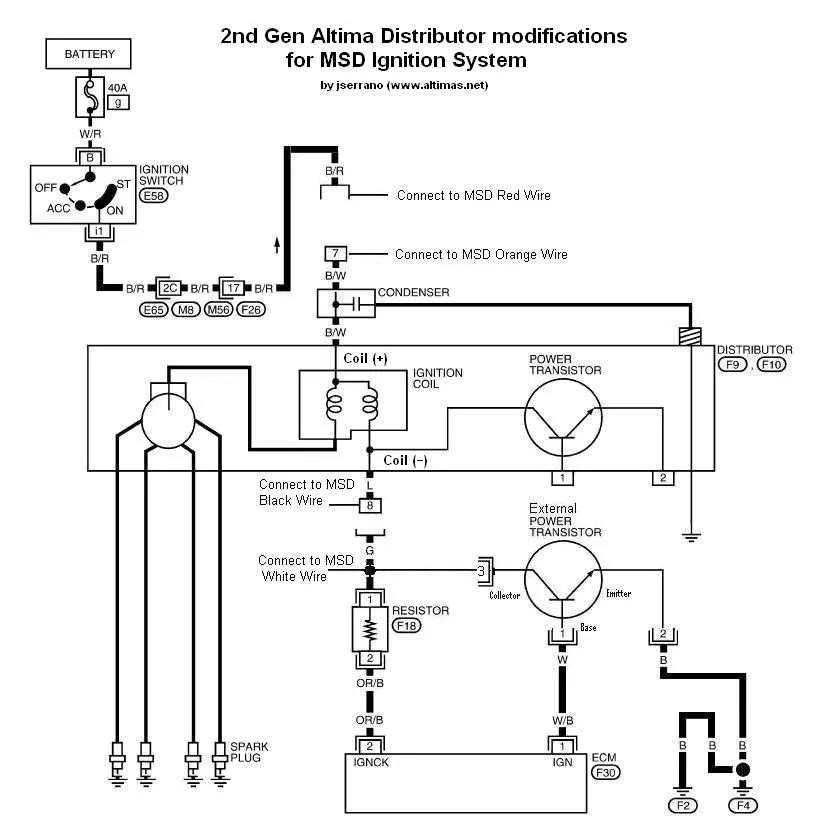
Ensure that each wire is securely connected to the correct terminal to avoid electrical failure. Begin by carefully identifying the primary power source and ground connections, as these are the foundation of the entire system. A stable connection to the battery or power relay is critical for reliable performance. Next, confirm that the distributor leads are routed without interference, keeping clear of heat sources and sharp edges that could cause wear over time.
Correct polarity is crucial when linking the control module to your power supply. Reversed connections can result in poor system performance or even permanent damage to sensitive components. Ensure that each terminal is properly labeled for clarity, reducing the risk of accidental miswiring during installation or repairs.
Double-check that all signal wires are routed to their corresponding ignition devices, ensuring the signal flow remains uninterrupted. Any improper connections may lead to incomplete spark generation or irregular timing. When working with the coil, avoid contact with exposed wires, and protect them with proper insulation. For an added layer of security, use protective fuses to safeguard against power surges and ensure longevity.
Pay attention to system grounding–a poor ground connection can lead to erratic functioning or total system failure. Always verify that the ground cable is clean, secure, and free of corrosion, as this is one of the most common causes of malfunction in high-performance ignition systems.
MSD Ignition Wiring Diagram: Practical Guide
When setting up your performance system, it’s crucial to connect the components properly to ensure reliable operation. Follow these steps for an efficient installation of your high-performance ignition system.
- Power Supply Connection: Start by routing a 12V power wire from the battery to the main unit. Ensure this wire is fused to protect the system from potential surges.
- Trigger Wiring: The trigger signal should be connected to the distributor or crank sensor. This signal tells the system when to fire the spark plugs, so accurate placement and a secure connection are vital.
- Coil Leads: Connect the primary coil leads from the unit to the coil itself. Make sure the polarity is correct, as reversing this can cause erratic performance or complete failure.
- Signal Grounds: Ground all the signal wires to the engine block or a solid chassis point. A poor ground connection can lead to inconsistent firing or misfires.
- RPM Limit Adjustments: If your system allows RPM limiters, adjust them according to your engine’s capabilities. Improper settings can result in engine damage if the RPM limit is set too high.
After connecting the necessary wires, double-check all terminals for tightness and inspect for potential short circuits. It’s always a good idea to use quality, insulated connectors to prevent any accidental grounding.
Before firing up your engine, verify the setup by using a multimeter to ensure correct voltage readings at key points, such as the coil, unit, and power supply connections. This will ensure that everything is functioning as expected and help avoid costly mistakes.
In case of troubleshooting, always refer to the specific component manuals for any manufacturer-specific adjustments or installation tips. Following these steps will help maximize the longevity and performance of your ignition setup.
How to Read and Understand the MSD Ignition Wiring Diagram

Start by identifying the power input. The main positive lead, usually marked as the “12V+” or similar, connects directly to your vehicle’s battery or a constant 12V source. This is crucial for powering up the system. Next, locate the ground terminal. The system requires a solid connection to the chassis or battery ground to complete the circuit. Improper grounding can cause erratic operation or failure to start.
Pay attention to the signal wires. The system typically uses a tachometer or a similar signal input to monitor the engine’s RPM. This wire is often connected to the vehicle’s distributor or a sensor, providing necessary feedback to the controller for timing adjustments. If the RPM signal isn’t properly routed, you won’t see accurate timing or performance changes.
Next, inspect the coil connections. These are usually high-voltage leads, and it’s essential to verify the correct orientation. The positive lead from the control unit connects to the coil’s negative terminal, while the output of the coil is routed to the spark plugs via high-voltage cables. Incorrect wiring here can lead to weak or inconsistent sparks.
The activation circuit is another key area. It connects to a switch or relay, often controlled by the ignition key or a push-to-start button. This part controls when the system powers up and sends signals to the coil. If there’s an issue with the activation switch, the system won’t power on, or you’ll experience startup delays.
Finally, check for any optional components such as a rev limiter or additional sensors. These devices add functionality but also require proper connection to ensure smooth operation. If these are wired incorrectly, it could limit your engine’s performance or cause unsafe conditions.
Common Electrical Issues and Fixes for Performance Systems

Start by checking the power supply to ensure it’s steady and free of voltage drops. A weak connection can lead to inconsistent spark generation. Inspect the main power wire from the battery and look for any signs of wear or corrosion. Replace any damaged or corroded connectors immediately to maintain proper voltage flow.
Another frequent problem is improper grounding. Ensure the ground wire is clean, free of rust, and tightly connected to the engine block or chassis. A loose or oxidized ground can cause misfires and erratic behavior in the system. For best results, use a dedicated ground point that’s directly connected to the engine block, not just a bolt or painted surface.
Check for shorts or broken connections in the trigger wire leading to the control module. A short can cause intermittent failures or complete system failure. If the trigger wire is damaged, replace it immediately and verify that it’s securely routed, away from high-heat areas that could cause insulation damage.
Overheating components can also affect system performance. Examine the distributor and coil, making sure they’re positioned away from excessive heat sources. If you notice any signs of heat damage, replace those components and install them with appropriate insulation to prevent further issues.
Verify that all connectors are tight and free from contamination. Dust, moisture, or oil can cause poor contact and lead to performance issues. Clean all connectors regularly and apply dielectric grease to prevent corrosion and maintain a reliable connection.
Ensure that the tachometer signal wire is properly connected and shielded from electromagnetic interference. A weak or incorrect signal can cause erratic RPM readings or system malfunction. Proper shielding and routing of the tach wire will help prevent this issue.
Step-by-Step Instructions for Installing MSD Ignition Wiring

1. Disconnect the battery: Start by disconnecting the negative terminal to ensure safety during the installation process.
2. Mount the ignition control box: Secure the unit to a solid surface near the engine bay, away from excessive heat sources or moisture. Make sure it is firmly in place to avoid vibrations.
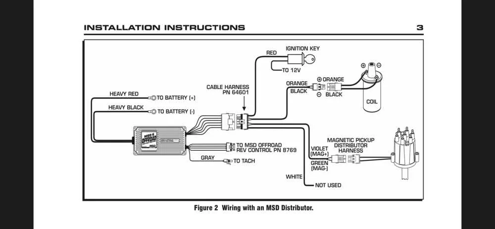
3. Connect the power wire: Attach the red wire from the control unit to the positive terminal of the battery or a suitable constant 12V source. Use a 30A fuse to protect the system from power surges.
4. Attach the ground wire: Connect the black ground wire from the control unit to the vehicle’s metal frame. Clean the surface where the wire will be attached to ensure a proper ground connection.
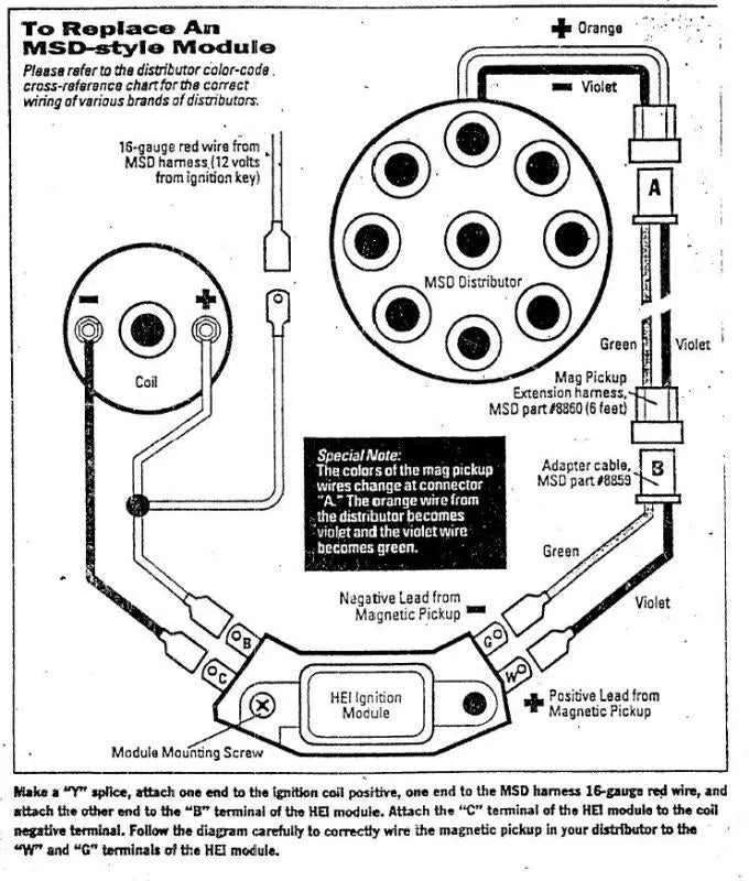
5. Wiring the distributor: Connect the green and violet wires from the control box to the distributor. Ensure that these are securely fastened to the terminals to prevent any loose connections.
6. Set up the tachometer lead: Use the provided tachometer wire and connect it to the control box’s tach output terminal. This allows the tachometer to monitor engine performance.
7. Install the coil: Connect the ignition coil to the appropriate terminals on the control unit. Follow the manufacturer’s instructions for coil wiring to ensure correct polarity.
8. Verify connections: Before reattaching the battery, double-check all connections. Ensure that no wires are exposed or prone to short circuits.
9. Test the system: Reconnect the battery and turn on the engine. Check for any irregularities in engine performance. If everything is functioning as expected, the installation is complete.