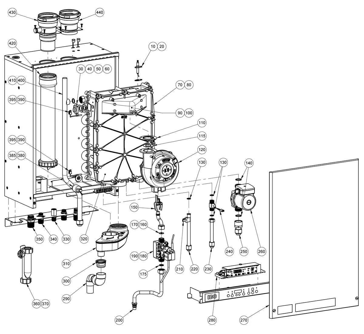
When analyzing the structure of a heating unit, focus on the main components responsible for energy transfer and circulation. Begin by identifying the fuel source input and its integration with the combustion chamber. This is essential for understanding how the unit generates heat efficiently. The heat exchanger plays a crucial role in transferring the generated thermal energy to the water or air used for heating purposes.
Next, examine the circulation pump, which maintains the flow of heated fluid throughout the system. The pressure relief valve ensures safe operation by preventing excessive pressure buildup. Additionally, the control unit is vital for regulating temperature, pressure, and fuel usage, maintaining optimal performance and safety throughout the heating cycle.
Finally, inspect the exhaust system, which directs combustion gases outside the building. Understanding the layout and function of these core elements is key to maintaining the system’s efficiency and longevity. Make sure to regularly check and service these components to avoid potential system failures.
Key Components of a Heating System Layout
The combustion chamber is central for fuel burning, where air and fuel mix to create the required heat. Efficient airflow and fuel management ensure maximum thermal efficiency.
The heat exchanger transfers thermal energy to water or steam. Proper sizing and material selection (often copper or stainless steel) prevent overheating and corrosion, improving longevity and performance.
The pump circulates heated fluids throughout the system. Proper flow rate and pressure management are essential to avoid system failures or energy losses.
Pressure and temperature gauges provide crucial real-time data, helping operators to monitor system health and avoid dangerous conditions like overheating or over-pressurization.
Safety valves prevent hazardous overpressure by releasing excess steam or water. Regular maintenance and testing guarantee proper functioning when needed.
Flue gas passages direct exhaust gases away from the system. Properly designed exhaust pathways minimize energy loss and ensure compliance with environmental regulations.
Control panels regulate operation. Programmable systems optimize fuel use, temperature, and flow rates, ensuring efficiency while reducing manual intervention.
Insulation reduces heat loss and improves energy efficiency. Ensure that all heated areas, especially pipes and tanks, are properly insulated to minimize waste.
Understanding the Feedwater System
Ensure the feedwater pump operates efficiently by maintaining proper pressure levels and checking for any leaks in the system. Use a high-quality, corrosion-resistant pump to prevent wear and ensure longevity. Monitor the temperature of the incoming water to avoid thermal shock, which can damage components. Regularly clean and inspect the preheating coils to prevent scale buildup, which can hinder heat transfer.
Install a deaerator to remove dissolved oxygen and prevent corrosion within the system. Properly balance the flow rate to maintain consistent water supply and pressure. Incorporate water treatment processes to avoid sediment accumulation and improve the lifespan of system components.
Install an automatic shutoff valve to protect the system from potential overpressure scenarios. Ensure that feedwater quality is consistently monitored to meet the necessary chemical treatment standards. Conduct regular inspections of the feedwater heater to optimize its performance and efficiency.
Identifying Key Components of the Combustion System
Start by locating the burner assembly, the central element for fuel ignition. This includes the fuel nozzles, which direct the fuel into the combustion chamber, and the ignition system, responsible for starting the fire. Check the fuel supply lines to ensure proper pressure and flow.
Next, identify the air supply system, consisting of the fan and damper controls, which regulate airflow into the combustion chamber. This is crucial for efficient burning. Ensure the air-to-fuel ratio is balanced to prevent incomplete combustion.
The combustion chamber itself is a critical area for monitoring. It is where the chemical reaction occurs, releasing heat. Inspect for adequate insulation to maintain high temperatures and reduce energy loss. Look for any signs of wear or buildup of residues that could affect performance.
Lastly, focus on the flue gas path, including the exhaust stack or vent, to ensure that waste gases are being properly expelled. Check the condition of the stack and ensure that all connections are secure to avoid leaks that could lead to safety hazards.
Analyzing the Control and Safety Mechanisms
Ensure continuous monitoring of key control devices to prevent system failures. Proper calibration of the pressure switch, temperature sensors, and flow controllers is essential for maintaining safe and efficient operation.
- Pressure Relief Valve: Test regularly to confirm it activates at the correct pressure level. This is crucial for avoiding overpressure situations that could lead to catastrophic failure.
- Flame Monitoring System: Implement regular inspections to verify that the flame detectors are responsive. Faulty detectors can cause incorrect fuel flow, leading to unsafe conditions.
- Low Water Cutoff: A critical safety feature that shuts down the system if water levels drop too low, preventing overheating and damage. Ensure it is cleaned and calibrated periodically.
- Fuel Supply Cutoff: This device must be regularly tested to ensure it functions in the event of a failure or emergency, preventing fuel leaks or explosions.
- Alarm Systems: Verify all safety alarms are functional and audible. Timely alerts are essential to initiate corrective action before a dangerous condition escalates.
Ensure that the control panel is user-friendly and displays real-time status updates on key safety mechanisms. It should allow operators to manually override systems in emergency situations. Keep an accurate maintenance log to track calibration dates and inspections, ensuring compliance with safety standards.