Tuning ArduPilot for your aircraft.
This version of the manual is just for the full navigation and . to switch into manual mode and recover.
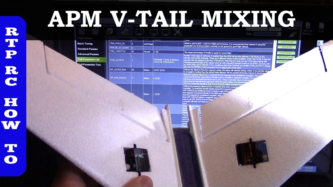
#define MIXING_MODE 0 //Servo mixing mode 0 = Normal, 1 = V-tail (v tail not. Please follow this manual to get familiar with the AP and to operate it correctly. The.
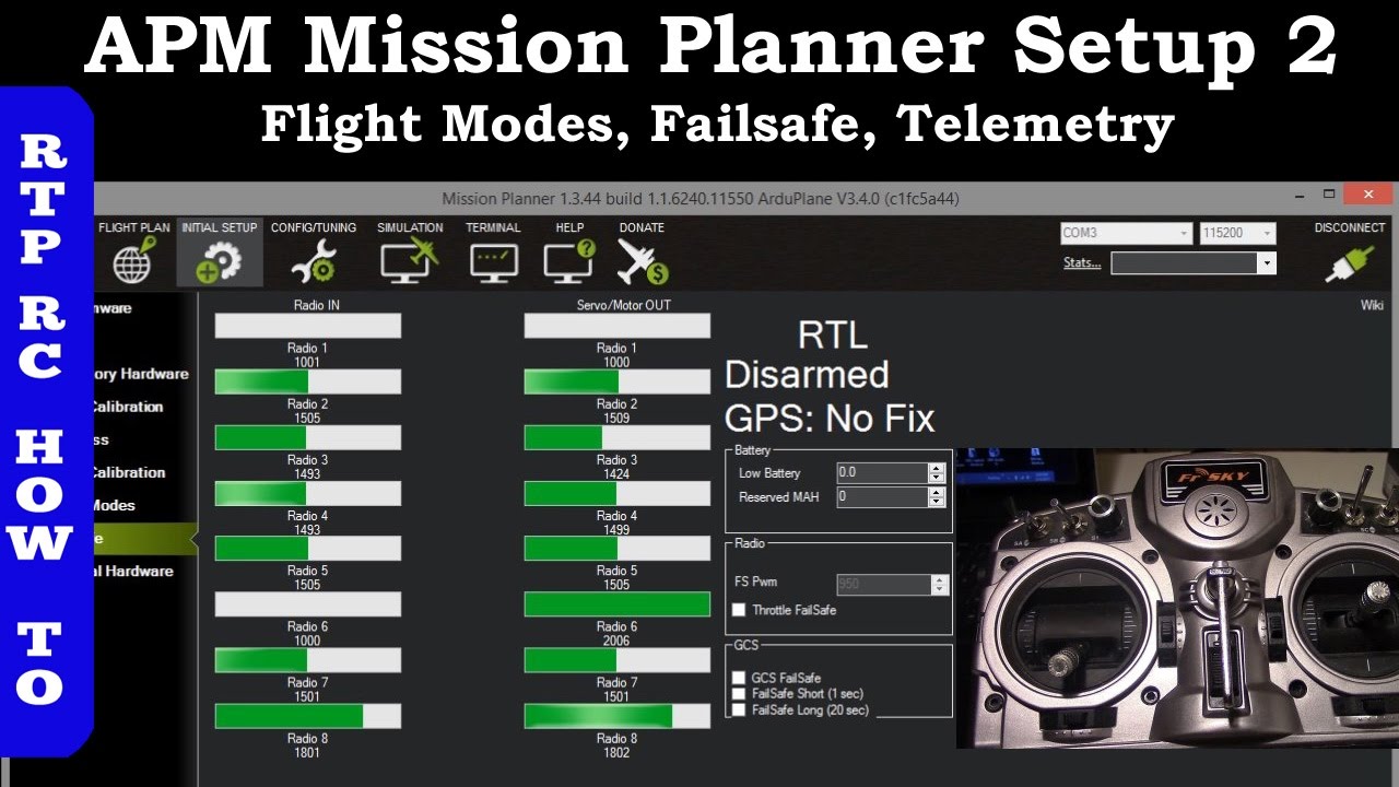
MFD AP You can use APM Mission Planner (a 3rd open source Normal, Wing (Ailvator), V-Tail. 2.
Wiring. * Please visit this link about wiring: http://youtu.
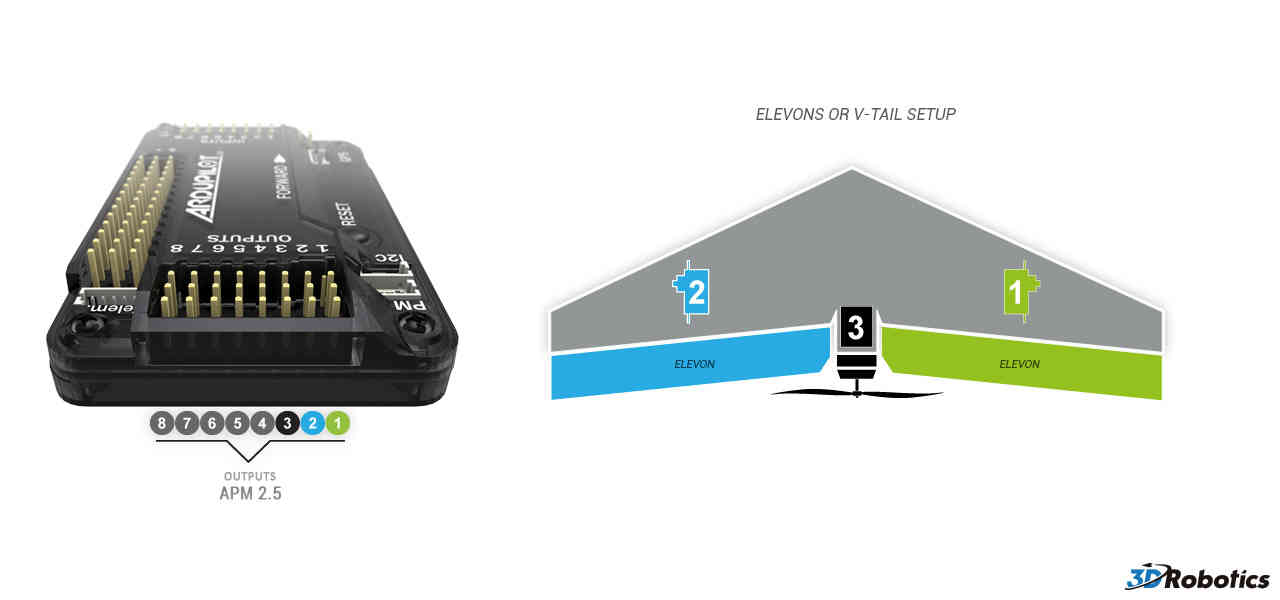
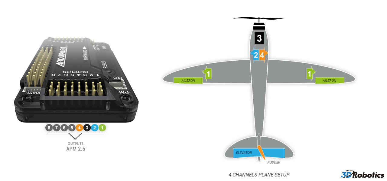
be/peX3BOoyPFk COPY AIL TO RUD Duplicate the AIL output to RUD port. Normal/Elevon/VTail Mode & Reversing Servos¶. There are a huge variety of control surface configurations possible in fixed wing aircraft, and ArduPilot supports.
Normal/Elevon/VTail Mode & Reversing Servos¶. There are a huge variety of control surface configurations possible in fixed wing aircraft, and ArduPilot supports.
Tuning ArduPilot for your aircraft. This version of the manual is just for the full navigation and . to switch into manual mode and recover.
#define MIXING_MODE 0 //Servo mixing mode 0 = Normal, 1 = V-tail (v tail not.APM Devo 7E tx Devo RX receiver mavlink mini OSD Ublox-6M GPS module Power module 3DR Radio Telemetry Mhz. F Quadcopter Hexacopter Frame XXDA 13T KV Motor XXD 30A ESC.
I have connected the receiver to the APM and the tx and tested / configured using mission planner, and connected the ESCs. questions are.
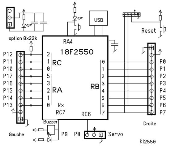
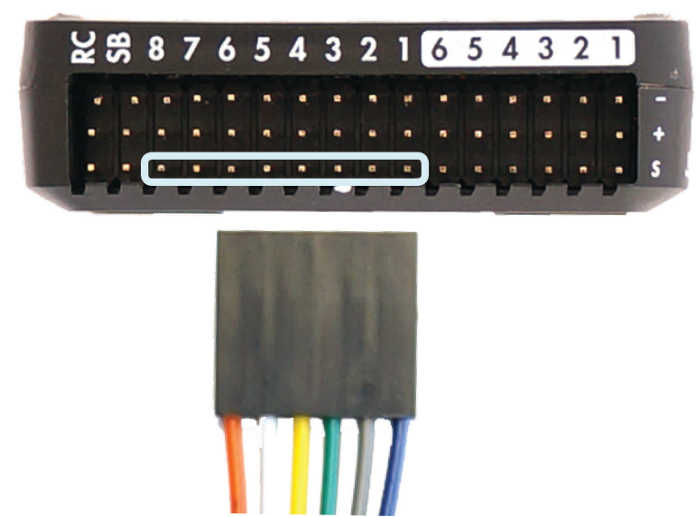
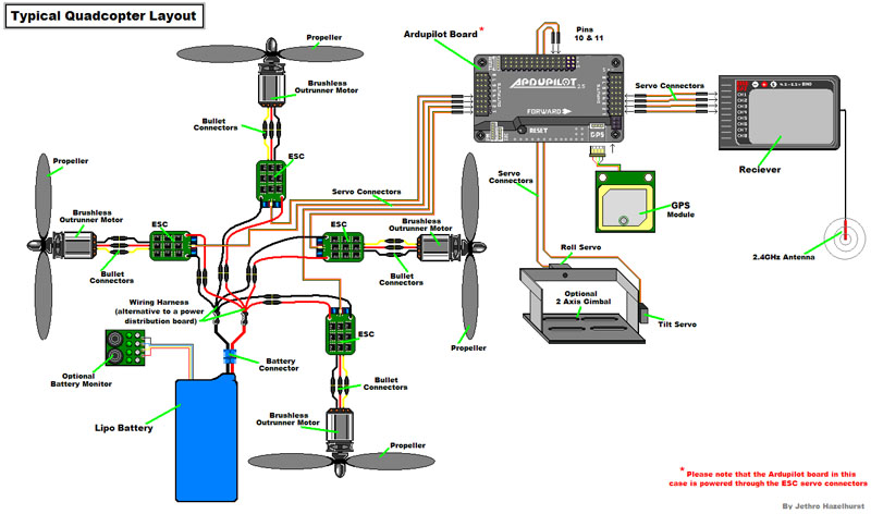
APM Wiring Diagram¶ The diagram below is an overview of how an APM2 can be connected to a receiver, ESC, GPS and even a camera gimbal. Connect the PDB multi-wire cable to APM Output Signal pins with the M1 wire connecting to the signal pin labeled 1, M6 and signal pin 6, etc.
See the above link for additional detail. Apm Wiring Diagram – Detailed Wiring Diagrams fresh apm 2 6 wiring diagram quadcopter balnearios co apm pinout apm 2 6 wiring Apm 2 5 Wiring Diagram – Could someone please direct me to a wiring diagram specific to each pin out (not block diagram) to the following: GPS Telemetry I2C.
and, pin out for each. APM Wiring Diagram¶ The diagram below is an overview of how an APM2 can be connected to a receiver, ESC, GPS and even a camera gimbal.
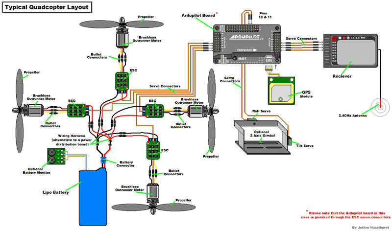
Connect the PDB multi-wire cable to APM Output Signal pins with the M1 wire connecting to the signal pin labeled 1, M6 and signal pin 6, etc. See the above link for additional detail. Sep 20, · Minim osd for apm I’ll like to add an osd on my q controlled by apm and would like to know if these parts will work with it. What alse i need to buy to connect all together?Archived:APM2.x Wiring QuickStart — Plane documentationAPM Wiring Diagram – Multirotors – ArduPilot Discourse
