For optimal engine performance, it’s essential to manage the supply of liquid to the injectors with precision. A vital component in this process is the device that maintains the appropriate flow dynamics and stability across varying engine conditions. This mechanism ensures that the system responds efficiently under different operating states, allowing for smooth acceleration and fuel economy.
The design of this component involves a spring-loaded assembly that adjusts the flow resistance in real-time based on system demands. When installed correctly, it maintains the necessary flow rate, preventing spikes or drops that could harm engine operation. To ensure maximum efficiency, the spring tension must be calibrated, considering factors such as engine size, expected power output, and environmental conditions.
When looking to install or replace this element, it’s crucial to carefully follow the configuration guidelines. Understanding the interaction between pressure inputs, return lines, and setpoints is key to ensuring the system operates at peak performance. Additionally, ensuring a proper seal between components will prevent leaks, which could otherwise result in inadequate delivery or wastage.
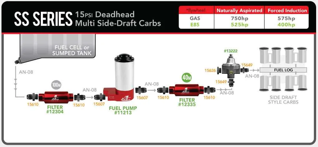
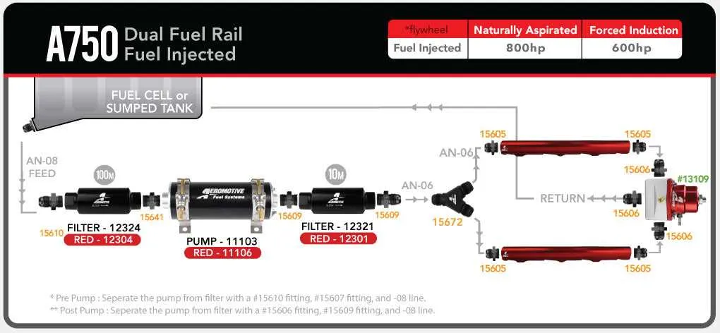
To visualize the entire system’s interaction, refer to the technical representation that clearly maps how the system adjusts based on varying input conditions. A thorough understanding of this layout is necessary for troubleshooting and fine-tuning the performance of the system in a wide range of applications.
Effective Management of Injector Flow Control System

For optimal engine performance, ensure precise management of the pressure within your system using a reliable control device. Follow these recommendations for improved operation:
- Install a unit with an adjustable flow mechanism to accommodate different fuel needs.
- Ensure the device is placed close to the intake, allowing for minimal pressure drop and stable operation under load.
- Use a unit designed to handle both high and low flow rates, ensuring flexibility for tuning purposes.
For the best results, consider these installation tips:
- Start by connecting the input port securely to the fuel source, ensuring no leaks.
- Ensure that the return line is properly installed to avoid excessive backpressure.
- Place the adjustment screw or mechanism within easy reach for fine-tuning.
Key troubleshooting steps:
- If you notice fluctuating readings, check the input and return lines for any blockages or leaks.
- Regularly inspect for wear and tear on the seals and diaphragms to maintain consistent performance.
Remember, proper calibration is essential for maintaining the right balance between flow and pressure, especially under varying driving conditions.
Understanding the Components of Fuel Management Devices
The spring-loaded diaphragm controls the flow of the liquid, adjusting it based on the system’s demands. The spring tension can be fine-tuned for more precise regulation of the amount allowed through the device.
Internally, a bypass valve maintains optimal operation. It diverts excess flow back to the tank, ensuring a steady supply without causing an overload in the system. The inlet port connects to the main supply line, while the outlet port leads to the engine’s injection system.
Most of these systems are equipped with a vacuum reference port. This feature helps to compensate for atmospheric changes, automatically adjusting the internal pressure to maintain balance. An additional feature commonly found in advanced models is a built-in gauge port, allowing for real-time monitoring of the internal conditions.
For the best performance, it’s crucial to mount these devices at a location with minimal vibration. This ensures consistent regulation, especially under high engine loads. Proper sealing and routing of lines also prevent unwanted fluctuations that could impair system efficiency.
How to Read an Aeromotive Fuel Pressure Regulator Diagram

Start by identifying the key components in the visual. The inlet and outlet ports are typically labeled, showing where the liquid enters and exits the system. These connections are crucial for understanding the flow direction and pressure control within the system.
Next, locate the adjustment screw. It’s essential for tuning the system, allowing users to set the desired level of restriction. The spring is another critical part, which works alongside the screw to maintain a consistent flow rate at different engine conditions.
The vacuum reference line is another significant feature. This line connects to the intake manifold, adjusting the restriction based on engine load. Understanding its placement is vital for ensuring the correct response under various operational states.
Pay attention to any arrows or directional markers that indicate the liquid’s movement through the device. These help clarify the flow path and prevent incorrect installation.
Lastly, check the sealing elements shown in the diagram. O-rings or gaskets are essential for preventing leaks and ensuring the system functions as intended without pressure loss.
Common Issues and Troubleshooting Tips for Fuel Flow Controllers
Check for leaks at all connections, especially around the base and fittings. Leaks can cause inconsistencies in performance. If you notice any drops of liquid or feel moisture around the unit, inspect the connections for tightness and replace seals as necessary.
Inconsistent flow regulation can occur if the internal diaphragm is damaged. This typically leads to unstable engine performance. If you suspect this, inspect the diaphragm for any signs of wear, cracking, or degradation. Replacing the diaphragm will restore proper function.
Incorrect idle speed often results from a faulty internal spring. If the idle speed fluctuates or becomes erratic, check the spring tension. If it’s stretched or weakened, it will need to be replaced to maintain consistent control.
Contaminated components can disrupt the movement of internal parts. Regularly inspect for debris or corrosion, particularly around the valve and housing areas. Cleaning the interior with an appropriate solvent can often resolve these issues without the need for a complete replacement.
Clogged ports can restrict the necessary flow. If you notice poor engine response or stalling, verify that all ports are clear. Cleaning or replacing blocked components can improve fuel management.
Incorrect setting may cause improper fuel flow regulation. Verify the settings according to manufacturer recommendations, especially when making adjustments or modifications. Over-tightening or under-tightening adjustments will lead to improper operation.
Erratic operation during acceleration is sometimes linked to improper vacuum line connection. Ensure that the vacuum line is free of cracks or blockages, and that it’s securely connected to avoid fluctuations in pressure.
Use of inappropriate parts can lead to premature failure. Always verify that the components are compatible with your engine specifications. Substituting low-quality or incorrect parts can result in malfunction and costly repairs.