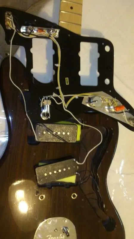
To achieve the best performance from your electric guitar, understanding the wiring of the active electronic components is crucial. This guide provides detailed instructions for proper setup, ensuring clarity and optimal sound output.
Start by identifying the key components–the control pots, the switch, and the active circuits. Be sure that the connections are solid and free of interference. The ground wire should be connected to the bridge or the designated grounding point on the guitar body to prevent hum or unwanted noise.
Ensure the signal flow follows the intended path: the active electronics will generally require a different type of configuration compared to passive systems. Begin with the power source–typically a 9V battery–and ensure the polarity is correctly aligned to avoid damage to the components.
For optimal performance, the tone and volume pots should be wired to their respective circuits, ensuring minimal resistance. Pay special attention to the connections between the pickups and the circuit board, as improper wiring can lead to weak signals or inconsistent tone.
Finally, make sure the soldering points are neat and secure. If possible, test the system before final assembly to ensure all components are functioning as expected. This prevents any surprises during performance or recording.
Wiring Guide for Modern Electric Guitar Components
For proper installation of the electronic elements in your guitar, follow these essential steps for correct signal flow and functionality.
- Start by securing the ground wire to the bridge to ensure a solid connection for electrical return. This is a crucial step to avoid hum.
- Connect the hot leads from the magnetic sensors directly to the volume and tone pots. Ensure each connection is firm and clean to avoid signal loss.
- For improved tone clarity, use a capacitor with the tone control. The value of the capacitor will vary depending on the desired tonal range, but typically a 0.022 µF capacitor offers good results.
- Route the leads from the pots to the output jack carefully. Ensure no wires cross over each other to avoid short circuits.
Test each step as you proceed, checking for continuity and proper grounding before moving to the next stage. If any connection is loose, re-solder it to guarantee a stable signal path.
Finally, ensure the input jack is securely attached, and check all connections again before closing the cavity. If everything is functioning, you should have a clean, noiseless setup with minimal interference.
Understanding the Wiring Layout for Active Electric Guitar Components
Start by identifying the key components: the control pots, selector switch, and signal path. Ensure that the ground wire from the components is securely connected to the output jack to avoid hum. The bridge and neck coils need to be wired in series, with the hot terminals connected to the tone and volume controls, while the ground terminals connect to the common ground. Pay close attention to the coil splitting setup–ensure the switching mechanism isolates the two coils when needed for single-coil operation.
For proper signal routing, use shielded cable for connections between the switch and potentiometers to minimize interference. The tone control is typically wired to the neck coil, with the capacitor placed between the tone pot and the ground. Volume adjustments should be made through a potentiometer that alters the resistance along the signal path. Carefully check the polarity and ensure the correct orientation for all components to prevent phase issues.
Before finalizing, test the wiring using a multimeter to confirm continuity and proper grounding. Additionally, verify that the switch correctly selects between different configurations, and that the tone control adjusts the frequency response as expected. If the guitar uses an active preamp, make sure the power supply connections are insulated to avoid short circuits. Properly grounding all components will ensure stable performance during play.
Step-by-Step Guide for Installing and Connecting Modern Magnetic Sensors

1. Start by removing the existing components from the guitar. Ensure you have a clean workspace, and take note of the orientation and connections of the original parts.
2. Prepare the new sensors by checking the color coding of the wires. Generally, the red wire corresponds to the positive terminal, while the black wire is the ground. Refer to the instructions provided with the sensors for confirmation.
3. Solder the ground wires of the sensors to the common ground point on the control plate or shield. This ensures proper grounding and prevents unwanted noise.
4. Connect the positive wire from each sensor to the corresponding terminal on the switch or volume pot. Depending on your setup, this could be the input terminal of the switch or potentiometer.
5. Solder the output wire from the switch or pot to the output jack, ensuring a secure connection. This will transmit the signal from the sensors to the amplifier.
6. Double-check all solder joints for security and reliability. A cold solder joint can cause intermittent connections and signal loss.
7. Reassemble the guitar, carefully placing the components back in place. Make sure no wires are pinched, and the sensors are securely positioned.
8. Test the setup by plugging into an amplifier and checking the functionality of each sensor. Adjust the controls to ensure proper tonal balance and signal strength.
Common Issues and Troubleshooting Tips for Active Pickup Wiring
Start by checking the battery. Active components rely on power, and a dead or weak battery will cause issues like low output or complete silence. Replace the battery with a fresh one and ensure proper orientation in the compartment.
If there is a significant drop in signal or distorted sound, inspect the solder connections. Cold or cracked joints can result in signal loss or interference. Use a multimeter to test continuity and reflow any suspicious connections.
Another common issue is hum or noise. This can be caused by poor grounding or electromagnetic interference. Ensure the ground wire is securely connected to the metal parts of the body and consider adding shielding in the control cavity to minimize external noise.
Check the pots and switches for wear. Over time, these components can wear out or accumulate dirt, causing crackling sounds or inconsistent volume/tone control. Clean them with a contact cleaner or replace if necessary.
| Issue | Potential Cause | Solution |
|---|---|---|
| No sound | Dead or improperly connected battery | Replace the battery and check for proper connections |
| Weak signal | Loose or cold solder joints | Inspect and reflow any suspect joints |
| Hum or noise | Poor grounding or interference | Check ground wire, add shielding if necessary |
| Crackling or erratic control | Dirty or worn pots/switches | Clean or replace pots and switches |
Finally, ensure that the components are compatible with each other. Mismatched impedance values between parts can cause improper signal processing. Always verify the specifications of each component before installation.