
The Airlift 3p manifold diagram is a visual representation of the Airlift 3p manifold system. The Airlift 3p system is a popular aftermarket air suspension system used in vehicles. It allows for precise control of the vehicle’s air suspension, allowing the driver to adjust the ride height and stiffness of the suspension.
The manifold is a central component of the Airlift 3p system. It houses the valves that control the flow of compressed air to and from the air springs, allowing the driver to control the suspension. The manifold diagram provides a detailed breakdown of the manifold, including the location of the valves and the flow of air through the system.
Understanding the Airlift 3p manifold diagram is essential for anyone looking to install, maintain, or troubleshoot the Airlift 3p system. It provides a visual reference for the various components and their connections, making it easier to identify and address any issues that may arise. Additionally, the diagram can be used as a guide when modifying or customizing the system, ensuring that any changes are made correctly and safely.
In conclusion, the Airlift 3p manifold diagram is a valuable resource for anyone working with the Airlift 3p system. It provides a visual representation of the manifold and its components, making it easier to understand and work with the system. Whether you are installing, maintaining, or troubleshooting the Airlift 3p system, the manifold diagram is an essential tool to have on hand.
The Basics of Airlift 3p Manifold Diagram
The Airlift 3p manifold diagram is an important tool for understanding the operation and components of an Airlift 3p manifold system. This diagram provides a visual representation of how the system works and helps in troubleshooting and maintenance.
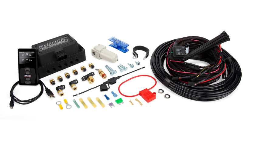
The Airlift 3p manifold diagram typically includes several key components, such as the air tank, compressor, valves, pressure switch, and air lines. These components work together to create an efficient and reliable air suspension system for vehicles.
1. Air Tank: The air tank is a reservoir for compressed air, which is stored and used to inflate the airbags in the suspension system. It is typically made of durable materials such as steel or aluminum to withstand high pressure.
2. Compressor: The compressor supplies compressed air to the air tank. It draws in air from the environment, compresses it, and pushes it into the tank. The compressor is powered by the vehicle’s electrical system.
3. Valves: The valves control the flow of air within the system. They open and close to allow air to enter or exit specific airbags or channels. The Airlift 3p manifold diagram shows the arrangement of these valves and how they connect to the air lines.
4. Pressure Switch: The pressure switch senses the air pressure in the system and automatically turns the compressor on or off to maintain the desired pressure level. It helps prevent over-pressurization and keeps the system running smoothly.
The Airlift 3p manifold diagram may also include additional components such as pressure gauges, dump valves, and fittings. These components enhance the functionality and versatility of the system, allowing for easy adjustment and control of the air suspension.
Understanding the basics of the Airlift 3p manifold diagram is crucial for anyone involved in the installation, maintenance, or repair of an Airlift air suspension system. It provides a clear overview of the system’s components and their interconnections, helping to ensure proper functioning and optimal performance of the system.
Understanding the Components of Airlift 3p Manifold Diagram
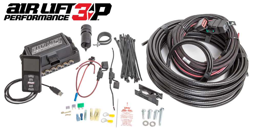
The Airlift 3p manifold diagram consists of several components that work together to effectively manage and control the air suspension system. These components include the air management controller, pressure sensors, solenoid valves, air lines, and air tanks. Understanding the function and connection of each component is crucial for the proper operation of the system.
Air Management Controller: The air management controller is the brain of the system. It is responsible for receiving input from the user and controlling the operation of the air suspension system accordingly. The controller allows the user to adjust the ride height and stiffness of the vehicle, as well as control other system functions such as lift and drop modes.
Pressure Sensors: Pressure sensors are used to monitor the air pressure in the air suspension system. They provide feedback to the air management controller, allowing it to maintain the desired ride height and adjust the air pressure when necessary. The pressure sensors are typically connected to the air lines or air tanks to measure the pressure accurately.
Solenoid Valves: Solenoid valves are responsible for controlling the flow of air in the system. They are usually connected to the air tanks and air lines and are controlled by the air management controller. The solenoid valves open and close to allow air to enter or exit the air suspension bags, adjusting the ride height of the vehicle.
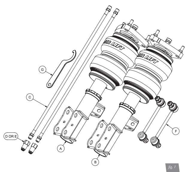
Air Lines: Air lines are used to carry the pressurized air from the air tanks to the air suspension bags. They are typically made of flexible rubber or plastic material to allow for easy installation and movement. The air lines are connected to the solenoid valves and the air suspension bags, ensuring a proper flow of air throughout the system.
Air Tanks: Air tanks are used to store the compressed air that is needed for the operation of the air suspension system. They are usually made of metal or heavy-duty plastic and are connected to the air lines and the compressor. The air tanks ensure that there is a sufficient amount of air available for the system to operate effectively.
In summary, the Airlift 3p manifold diagram consists of crucial components such as the air management controller, pressure sensors, solenoid valves, air lines, and air tanks. Each component plays a vital role in the operation and control of the air suspension system, allowing for adjustable ride height and enhanced performance.
Installation Process of Airlift 3p Manifold Diagram
Installing an Airlift 3p manifold diagram for your vehicle’s air suspension system is a straightforward process that can be completed with basic tools and some mechanical knowledge. The manifold diagram is an essential component that controls the air pressure and airflow within the system, allowing you to adjust and control the suspension settings of your vehicle.
Before you begin the installation process, it is crucial to familiarize yourself with the layout and components of the Airlift 3p manifold diagram. The diagram typically consists of an aluminum block with multiple ports, labeled for inflation and deflation valves, pressure sensors, and air line connections.
To install the Airlift 3p manifold diagram, follow these steps:
- Prepare the vehicle: Begin by securing the vehicle on a level surface and disconnecting the battery to prevent any electrical hazards.
- Locate a suitable mounting location: Find a suitable location within the engine bay or interior of the vehicle to mount the manifold. Ensure that it is easily accessible and protected from any potential damage.
- Mount the manifold: Use the provided mounting brackets and screws to secure the manifold in the chosen location. Make sure it is firmly attached and does not interfere with any other components.
- Connect air lines and sensors: Attach the appropriate air lines and pressure sensors to their corresponding ports on the manifold. Use the provided fittings to ensure a secure and leak-free connection.
- Connect power and ground: Connect the power and ground wires from the manifold to the vehicle’s electrical system. Follow the manufacturer’s instructions for proper wiring and use appropriate connectors.
- Test the system: Once the manifold is securely installed and all connections have been made, test the system for any leaks or malfunctions. Inflate and deflate the airbags to ensure proper functionality. Adjust any air pressure settings as needed.
It is important to consult the manufacturer’s instructions and guidelines specific to your vehicle and the Airlift 3p manifold diagram during the installation process. Following these steps and taking necessary precautions will help ensure a successful installation and optimal performance of your air suspension system.
Maintenance and Troubleshooting of Airlift 3p Manifold Diagram
The Airlift 3p manifold diagram is an essential component in the operation of an airlift system. It is responsible for controlling the flow of air and water in the system, ensuring proper circulation and efficiency. However, like any mechanical system, it requires regular maintenance and occasional troubleshooting to ensure optimal performance.
One common maintenance task for the Airlift 3p manifold diagram is inspecting and cleaning the valves and tubing. Over time, dirt, debris, and mineral deposits can accumulate, leading to clogs or restricted flow. Regular inspection and cleaning can prevent these issues and maintain the smooth operation of the system. If any damage or wear is detected during the inspection, it is crucial to replace the affected components promptly.
Another aspect of maintenance is ensuring proper alignment and connection of the manifold diagram. Any misalignment or loose connections can result in leaks or inconsistent airflow, affecting the overall performance of the airlift system. Regularly checking and tightening the connections can help prevent these issues. It is also recommended to replace any worn or damaged gaskets or seals to maintain a reliable and efficient system.
When troubleshooting the Airlift 3p manifold diagram, one common issue to check for is air leaks. Air leaks can occur around the valves, connections, or tubing, disrupting the flow of air and water. Visual inspection or using a soapy water solution can help identify any air leaks. Once identified, the leaks can be sealed using appropriate sealants or by replacing faulty components.
If the airlift system is experiencing uneven air distribution or poor water circulation, it may be necessary to adjust the flow control valves on the manifold diagram. Proper adjustment of these valves allows for a balanced distribution of air and water, optimizing performance. It is recommended to consult the manufacturer’s instructions or seek professional assistance for precise valve adjustment.
In summary, regular maintenance and troubleshooting of the Airlift 3p manifold diagram are crucial for maintaining the efficient operation of an airlift system. Regular cleaning, inspection, and alignment checks can help prevent issues such as clogs, leaks, and uneven airflow. Additionally, troubleshooting common issues like air leaks or poor circulation can be addressed by proper sealing or valve adjustment. By following these maintenance practices, the airlift system can continue to provide efficient and reliable performance.
Benefits of Airlift 3p Manifold Diagram
The Airlift 3p manifold diagram offers various benefits for both residential and commercial applications. Here are some of the key advantages:
1. Enhanced Control: The Airlift 3p manifold diagram provides a centralized control system for managing air suspension setups. Users can easily adjust the pressure and ride height of their vehicles to achieve optimal performance and comfort. This level of control allows for precise tuning and ensures a smooth and level ride at all times.
2. Improved Safety: By using the Airlift 3p manifold diagram, drivers have better control over their vehicle’s suspension, which can improve safety on the road. The ability to adjust ride height and pressure can help compensate for different loading conditions, ensuring better handling and stability. This is especially important for vehicles that are frequently loaded with heavy cargo or towing trailers.
3. Customizable Presets: The Airlift 3p manifold diagram allows users to save and recall multiple presets for different driving scenarios. Whether you need a lower ride height for track days or a higher one for off-road adventures, you can easily switch between presets with the push of a button. This level of customization ensures that your vehicle’s suspension is always tailored to your specific needs and preferences.
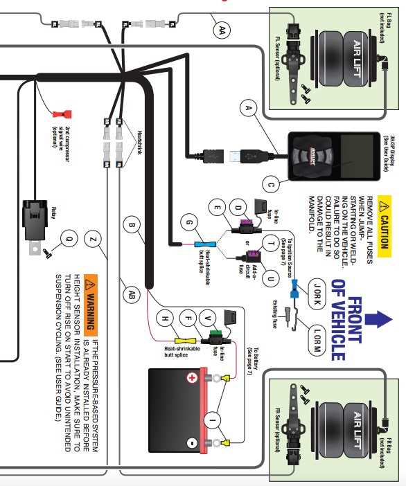
4. Easy Installation: The Airlift 3p manifold diagram is designed for easy installation, making it accessible to both DIY enthusiasts and professional installers. The detailed wiring diagram and user-friendly interface simplify the process, reducing installation time and eliminating guesswork. This means that you can start enjoying the benefits of the Airlift 3p system sooner.
5. Compatibility: The Airlift 3p manifold diagram is compatible with a wide range of air suspension systems, making it a versatile choice for different vehicles and applications. Whether you have a car, truck, SUV, or even a motorcycle, you can take advantage of the benefits offered by the Airlift 3p manifold diagram.
In conclusion, the Airlift 3p manifold diagram offers enhanced control, improved safety, customizable presets, easy installation, and compatibility with various air suspension systems. Whether you’re looking to enhance the performance of your vehicle or simply want a more comfortable ride, the Airlift 3p manifold diagram is a reliable and practical solution.
Q&A:
What is an Airlift 3p Manifold Diagram?
An Airlift 3p Manifold Diagram is a visual representation of the pneumatic system used in an Airlift 3p suspension system. It shows the connections and flow of air between the different components of the system.
What are the benefits of using an Airlift 3p Manifold Diagram?
Using an Airlift 3p Manifold Diagram provides several benefits. It helps in understanding the layout and functioning of the pneumatic system, making it easier to troubleshoot any issues that may arise. It also aids in the installation process, ensuring that all components are connected correctly. Additionally, it can serve as a reference for future modifications or upgrades to the system.
How is an Airlift 3p Manifold Diagram helpful in troubleshooting?
An Airlift 3p Manifold Diagram is helpful in troubleshooting as it provides a clear visual representation of the pneumatic system. By referring to the diagram, one can easily identify any potential issues with the connections or flow of air. This can save time and effort in diagnosing and fixing problems.
Can an Airlift 3p Manifold Diagram be customized?
Yes, an Airlift 3p Manifold Diagram can be customized according to the specific setup of the pneumatic system. It can include additional components or modifications made to the system. Customizing the diagram ensures that it accurately represents the layout and connections of the actual system being used.
Where can an Airlift 3p Manifold Diagram be obtained?
An Airlift 3p Manifold Diagram can be obtained from the manufacturer or distributor of the Airlift 3p suspension system. It may be available in the product documentation or can be requested separately. Online resources and forums dedicated to automotive suspension systems may also provide diagrams or resources related to the Airlift 3p Manifold Diagram.
What are the benefits of Airlift 3p Manifold Diagram?
Some of the benefits of Airlift 3p Manifold Diagram include: easy installation, precise control of air suspension, enhanced ride quality, improved handling and stability, ability to adjust the ride height, and compatibility with various air suspension components.