Testing the Circuit Board Output. To use the Balboa Quick Check Changing a System Circuit Board.
How to Remove a System Circuit. If you are looking for a manual for a topside panel of system control please go here first. Balboa Direct and Balboa Water Group products are intended to be installed or (and French) · Standard Air Controls, & (and French).
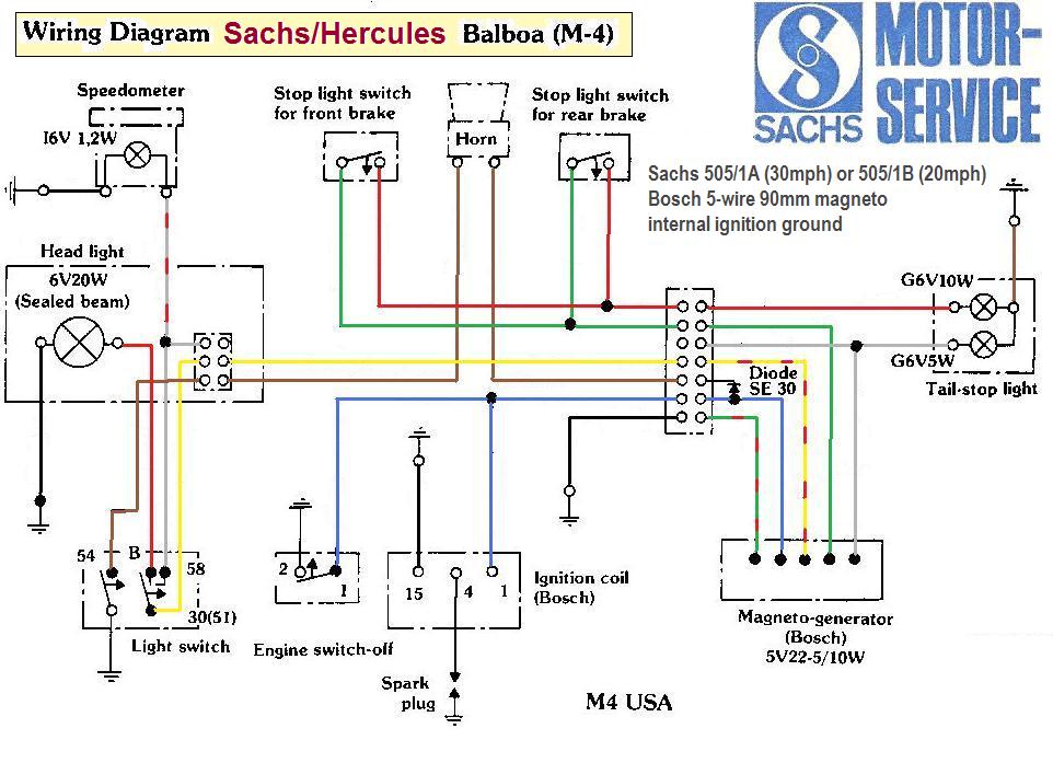
Initial release – BP with MicroSilk®. System Wiring Diagram .
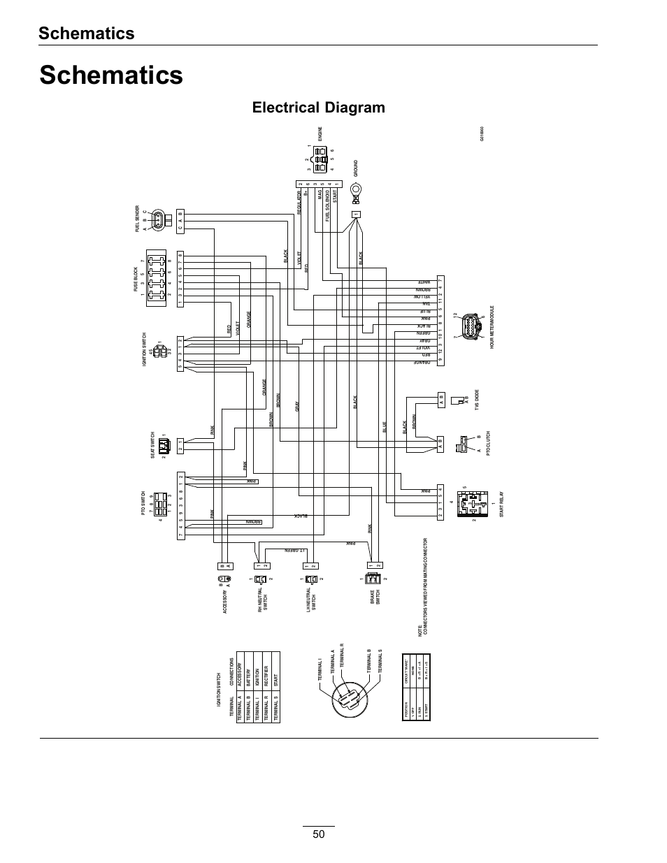
While the system is running, move DIP Switch 1 (on S1 on the Main circuit board) to ON. BP with TP topside; BP with TP topside; BP wiring diagram; What the / tp system looks like if you buy wif-fi add-; BP with.
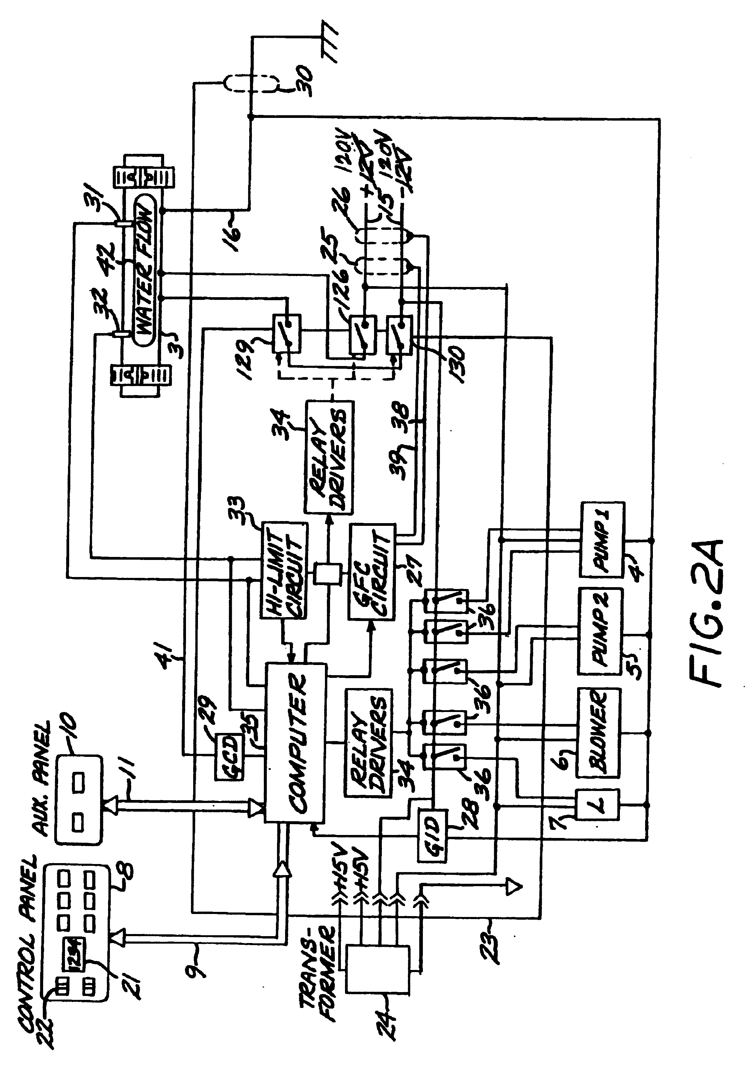
schematron.org IMPORTANT – Service must include a neutral wire, with a line to neutral Wiring Diagram . While the system is running, move DIP Switch 1 (on S1 on the Main circuit board) to ON.
. Contact Balboa if you require additional configuration pages added to this tech sheet.Balboa Ozone Generator.
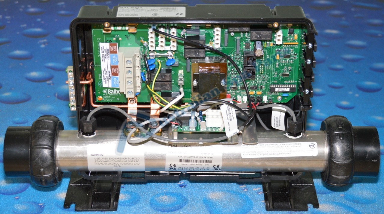
Be careful with the orientation of the connector and notice the flat sides on the outer two prongs. Generally black and white wires used on the old unit will indicate V operation and Black and Red wires will indicate V operation. Confirm this with markings on the old unit and the wiring diagram inside the system box.

These application notes have been created by individuals with a great deal of experience and expertise in the hot tub industry. Hot tub manufacturers that adhere to these recommended industry practices will ultimately improve the quality and reliability of the control system and will experience greater performance and longevity throughout their entire product line.

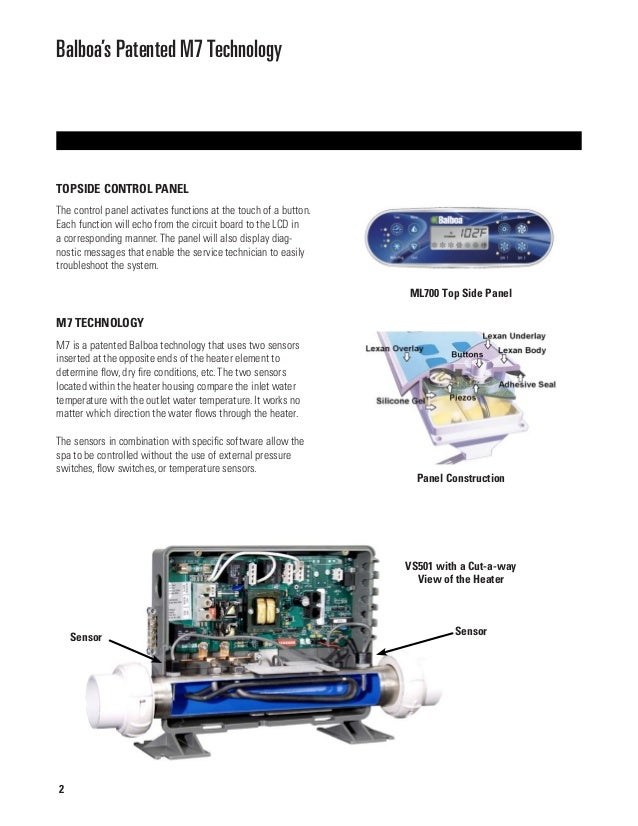
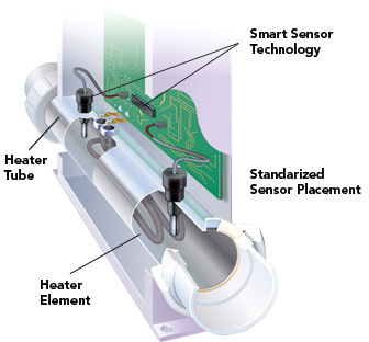
Includes Balboa’s patented overheat Fault Detection for runaway pumps or stuck relays. The new M7 Plus software design incorporates patented technology using a microprocessor to intelligently monitor the hot tub water temperature and detect a runaway pump or stuck relays.
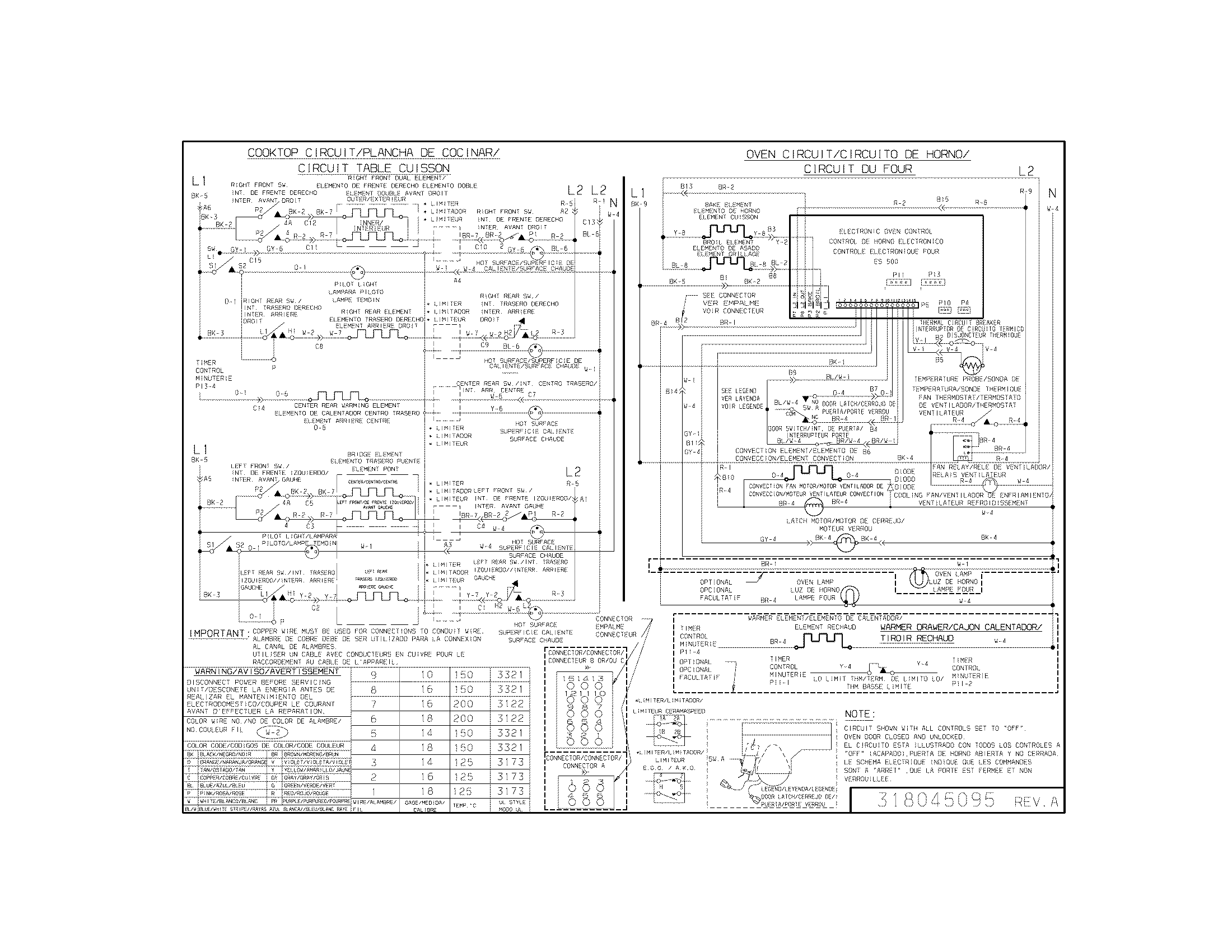
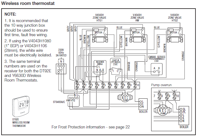
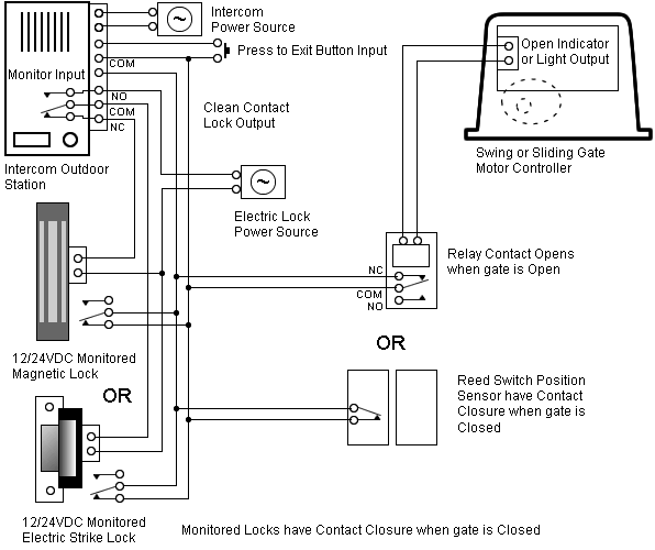
Always refer to the wiring diagram which is included inside each system, located on the back side of the system to the main terminal block. The wiring diagram inside the system box shows the main terminal block as TB1.
Important Using non-copper wire can be dangerous, and also can schematron.org 7 Wiring Check for G.F.C.I. Balboa Direct and Balboa Water Group products are intended to be installed or repaired by a licensed professional technician.
Improper use or installation could result in injury or death! Just click on the tab for the type of product you are looking at to see all availible manuals.Balboa Water Group – M7® Application GuidelinesBalboa Water Group – Manual & Instruction Sheets
