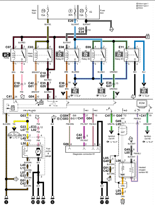
schematron.org Manual: Table 1 Diagram to Use with Unit and Vents .. 3.
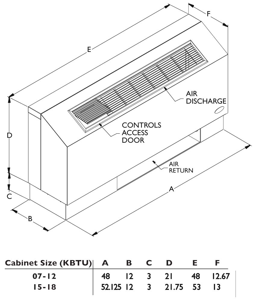
Table 2 . Low Voltage Wiring Diagram: Heat Pump.
Bard I-TEC rules the school.
1 of LOW VOLTAGE. CONTROL CIRCUIT WIRING schematron.org Manual No.: Table 1 Diagram to Use w/Unit & Vents .
Bard Transformer Tap
3. all portions addressing “installation” are for reference only. ECONOMIZERS ..
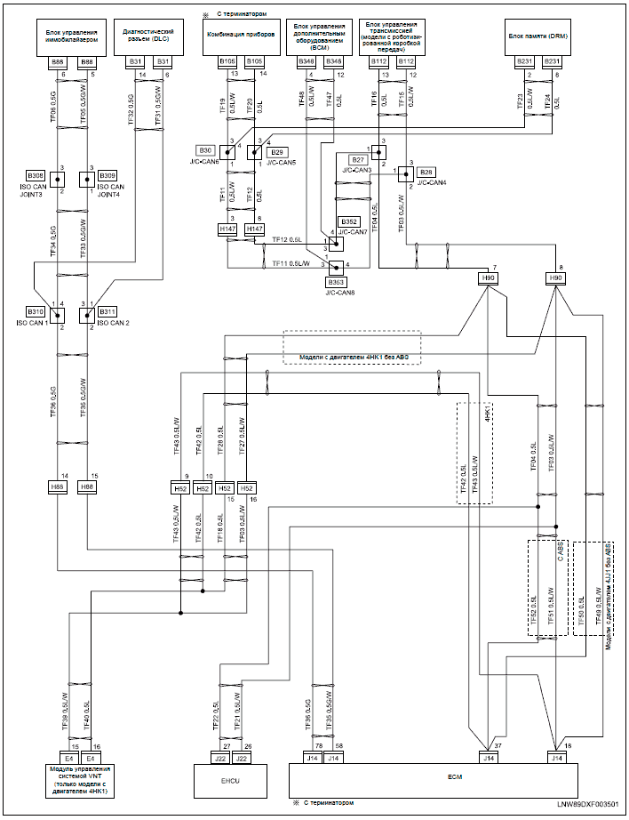
control wiring diagrams for single unit applications. Refer to.
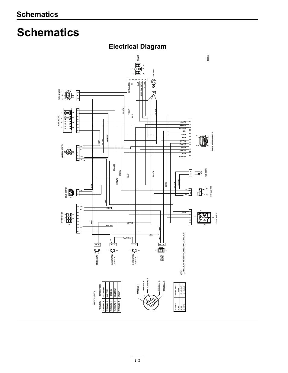
INSTALLATION INSTRUCTIONS. LOW VOLTAGE Bard Manufacturing Company, Inc. Bryan, Ohio Figure 11 Wiring Diagram.
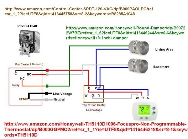
The links below are to current Bard product wiring diagrams. All documents are in PDF format and will require Acrobat Reader. If you do not have this software.Fast Track Shipping [Add $]Ships out your order(s) next business day after order is paid for in full.
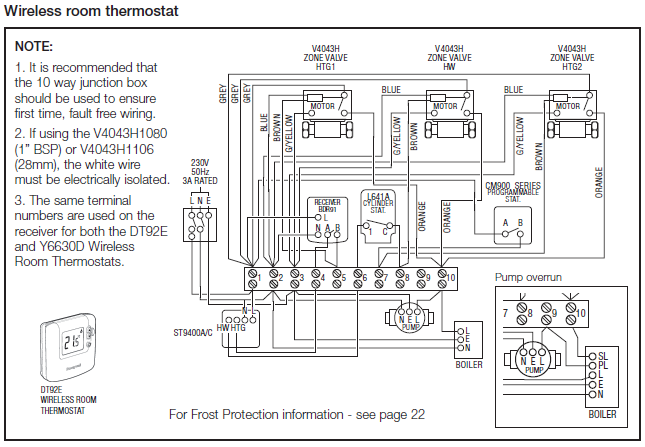
Your order(s) typically arrive to your shipping address in no more than 4 business days East Coast, and 7 business days for the West Coast/Midwest. system thermostat, sensors and appropriate schematron.org TEMP thermostat is the system controller and works much like a room thermostat, but provides for communicating control.
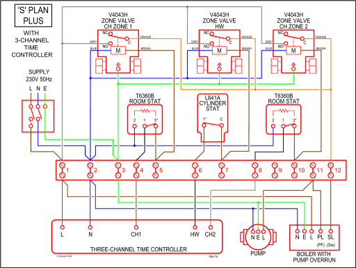
Wiring (Part # ) NOTE: This is the preferred method. 1. Before doing any wiring, disconnect the negative battery terminal.
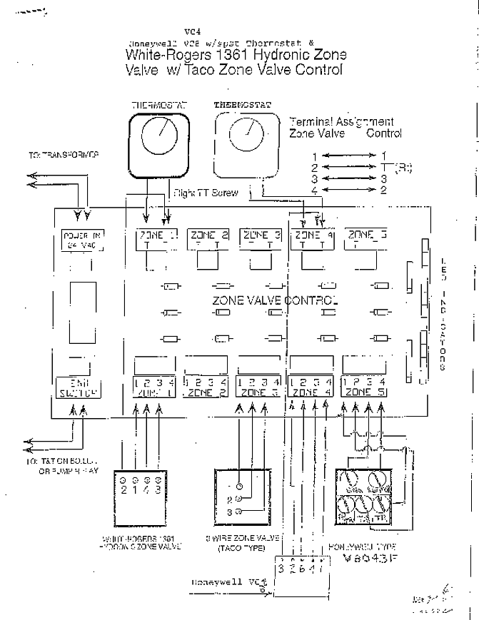
2. Mount the included switch with harness in desired location. Note: Read instructions entirely before installing and using this product.
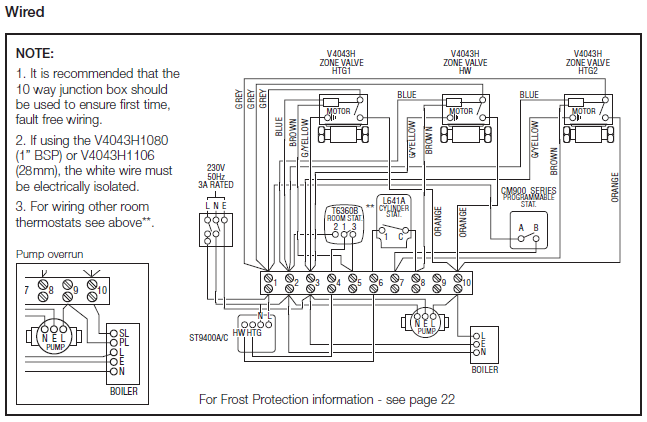
Light Bars and Wiring Kits are . I have a Bard Model I have a Bard Model #PHA with an electric emrgency heat strip installed and am installing a new Honeywell Model #RTHC non programmable digital thermostat. Everything works except the compressor and outdoor fan comes on momentarily when the thermostat calls for heat, but then shuts off after a few seconds.
Electrical Diagrams for Heater Connections 12V Application: Dual Volt 3-Wire Heater PFT Models With Pressure Switch & Electrical Harness 19 .How to Wire a Thermostat | Wiring Installation InstructionsSnap On Parts Diagrams – Engine Diagram And Wiring Diagram