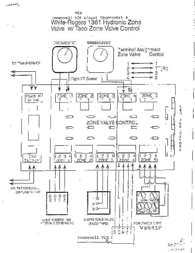
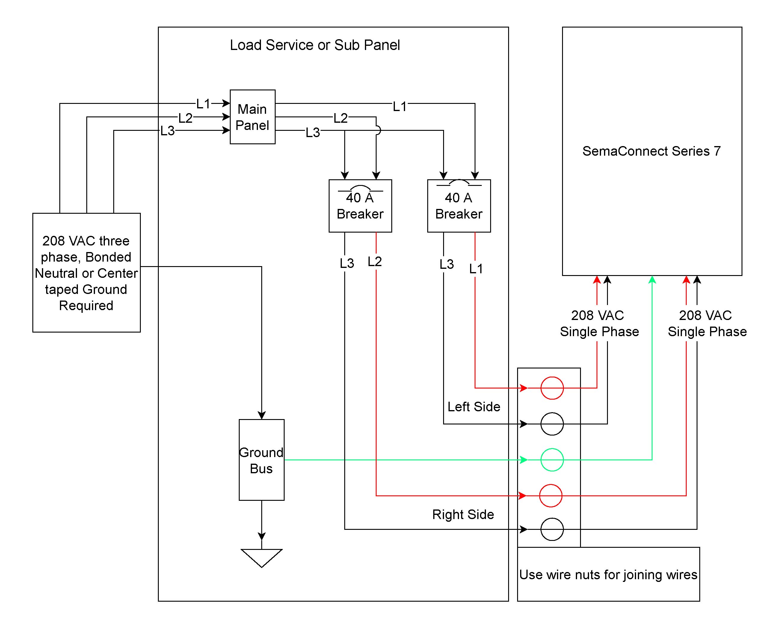
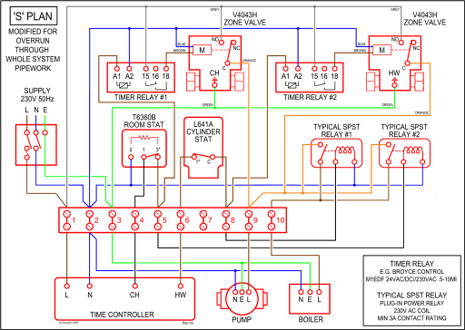
Since Ken has a bit of a wiring phobia, he enlisted rotary friend Gabe on this job, having printed out a large schematic for the PS wiring.
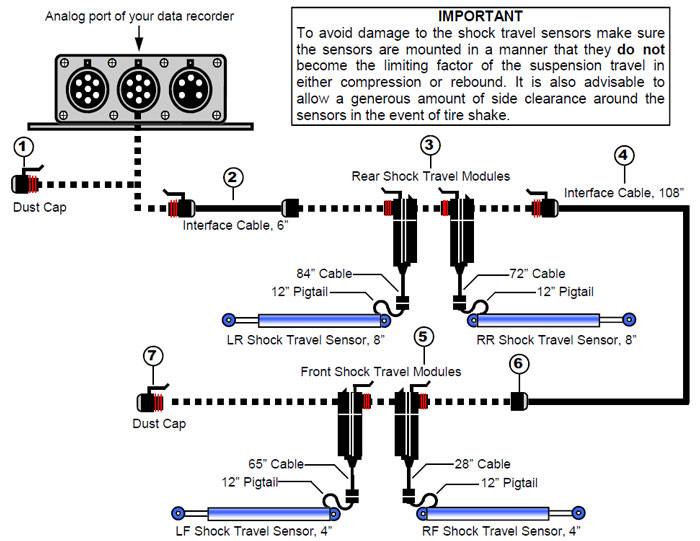
Competition Systems, Inc/Racepak make no representations or warranties of any type with .. secondary/digital input wiring harness connects to this port. The following downloads contain instruction manuals and firmware updates for your particular Racepak Data schematron.org be sure to select the proper.
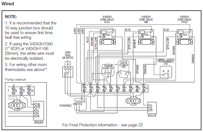
View and Download Racepak IQ3 installation manual online. IQ3 Street Dash Installation Manual IQ3 Street Dash Wiring Pinout Connector Pinout Description.
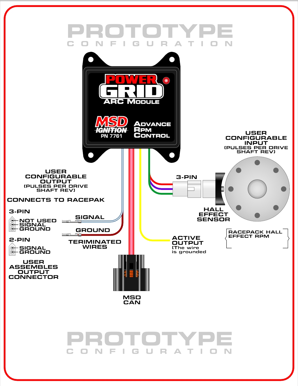
are met. mA ground sink maximum. External Programming Button and Fan output Wiring Diagram.
BUTTON WIRING DIAGRAM chassis ground or. IQ3 pin 4 .If you are using a Racepak Pro II, Pro I, Pro IA, SC, 2K-3K, or 4K, you will require a different manual.
Page 2: Recording A Run. V / V / V RECORDERS One of the first functions you will perform with your Racepak data recorder is to record a run.
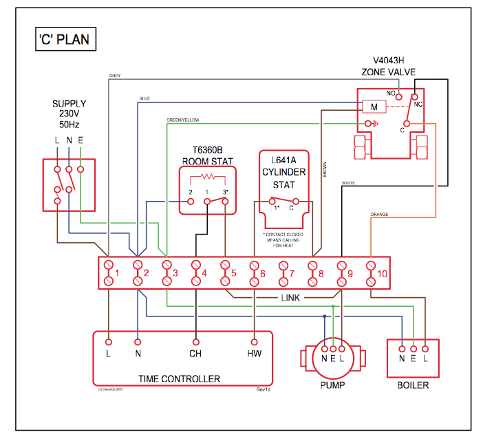
Nov 17, · Racepak V Wiring Diagram Posted on Nov 17, by Jim Shepherd You can also find other images like wiring diagram, parts diagram, replacement parts, electrical diagram, repair manuals, engine diagram, engine scheme, wiring harness, fuse box, vacuum diagram, timing belt, timing chain, brakes diagram, transmission diagram, and engine problems. The oil fill on the sie of the case was drilled larger and tapped for approx 1″.
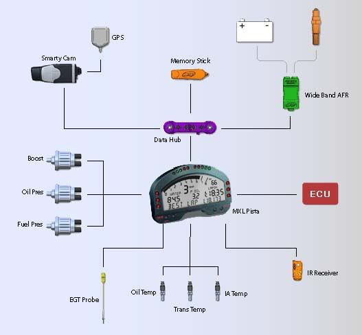
Then a 1″ stud was center drilled & tapped for the Racepak 3/8 sensor. Also the 1″ stud was countersunk on the outside end to allow clearance for the moldend rubber where the wire goes into the sensor. The following downloads contain instruction manuals and firmware updates for your particular Racepak Data schematron.org be sure to select the proper hardware below: G2X, G2X Pro, Universal EFI Module, IQ3, SmartWire or Drag Racing System.
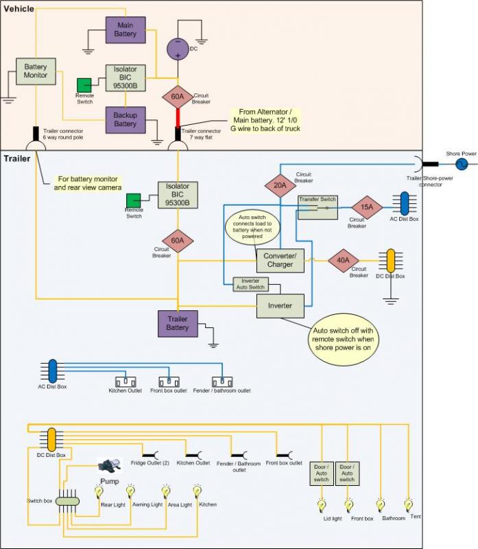
Vantage CL1. Jun 27, · ECU CAN Bus wiring diagrams Post by bmpnumber1» Sat Mar 12, am Let me see if I can put this down accurately: I have recently acquired the IQ3 Display dash and with it came two different wiring diagrams and have also been pointed to a third wiring diagram from the Haltech website concerning the CAN bus.Wiring Racepak IQ3 can connector – schematron.org – Mazda RX7 ForumRacepak Wiring Diagram – schematron.org
