
If you’re into automotive electrical systems or tinkering with your vehicle’s wiring, chances are you’re familiar with Bosch relays. These devices are commonly used to control high current circuits in various applications, such as automotive lighting, air conditioning, and power accessories. One popular model is the Bosch relay 0332, which offers reliable and efficient performance.
In this article, we will delve into the Bosch relay 0332 wiring diagram. Understanding the wiring diagram is crucial for anyone looking to install or troubleshoot electrical systems that use this relay. We will break down the different components of the relay and explain how they should be connected, providing a step-by-step guide for a hassle-free wiring experience.
First, let’s talk about the basics. The Bosch relay 0332 is a four-pin relay designed to handle high currents up to 30 amps. It features a normally open (NO) contact, a normally closed (NC) contact, a common (COM) contact, and a coil. The coil is energized by a low current signal, allowing the relay to switch the high current circuit on and off. By understanding the wiring diagram, you will be able to correctly connect these pins to different electrical components.
Understanding Bosch Relay 0332: A Comprehensive Wiring Diagram Guide
Bosch relay 0332 is a widely used relay in automotive and industrial applications. It is a versatile and reliable relay that can be used for various purposes, including controlling high current loads, switching devices, and providing protection against overvoltage or overcurrent conditions. In this wiring diagram guide, we will explore the different components and connections involved in setting up an electrical circuit with the Bosch relay 0332.
Before we dive into the wiring diagram, let’s first understand the basic components of the Bosch relay 0332. The relay consists of several terminals, including the coil terminals, the normally open (NO) and normally closed (NC) contacts, and the common (COM) terminal. The coil terminals are used to energize the relay and switch the contacts. The NO and NC contacts act as switches that open or close the circuit depending on the relay’s state. The COM terminal is the common connection point for the contacts.
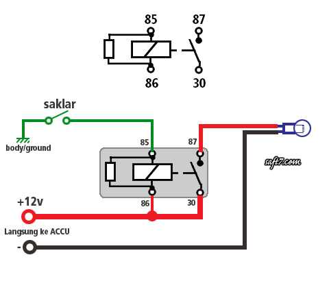
Now, let’s move on to the wiring diagram and how to connect the Bosch relay 0332 to an electrical circuit. Firstly, you need to identify the power source and load that you want to control using the relay. The power source is usually connected to the COM terminal, while the load is connected to either the NO or NC terminal, depending on whether you want the circuit to be normally open or normally closed.
Next, you need to connect the coil terminals of the relay to a power source that can provide the necessary voltage and current. One of the coil terminals should be connected to the positive side of the power source, while the other terminal is connected to the negative side or ground. This completes the circuit for the coil, allowing it to be energized and switch the contacts.
It is important to note that you may need to use additional components such as diodes, resistors, or capacitors depending on your specific application requirements. These components can help protect the circuit from voltage spikes, provide proper current limiting, or improve the overall performance of the relay.
In summary, understanding the wiring diagram and components of the Bosch relay 0332 is crucial for its proper installation and operation. By correctly connecting the power source, load, and coil terminals, you can effectively control various electrical circuits with this versatile relay. Additionally, considering the use of additional components can enhance the reliability and performance of the relay in your specific application.
Functionality and Applications
The Bosch relay 0332 is a versatile electrical component that offers reliable performance and robust functionality. It is commonly used in automotive and industrial applications to control high-current electrical circuits. The relay is designed to switch high currents with minimal power loss, making it suitable for various applications where power control is required.
One of the key functionalities of the Bosch relay 0332 is its ability to control the flow of electrical current based on an external input signal. This means that the relay can be used to automate specific electrical operations, such as turning on/off lights, motors, or other electrical devices. The relay acts as a switch, allowing or blocking the flow of current depending on the input signal it receives.
The Bosch relay 0332 is commonly used in automotive applications, such as in the control of the vehicle’s lighting system, cooling fans, and fuel pump. Additionally, it is also used in industrial settings, where it can be employed in motor control, process automation, and various other electrical control systems.
The relay’s wiring diagram demonstrates how it can be connected to a power source, load, and control signal. The relay features multiple terminals that are labeled for easy identification and proper connection. Understanding the wiring diagram is essential for proper installation and operation of the relay in different applications.
In conclusion, the Bosch relay 0332 offers reliable functionality and is widely used in automotive and industrial applications. Its ability to control high-current electrical circuits based on external input signals makes it a versatile component for various electrical control systems. By understanding its wiring diagram and proper connection, the relay can be effectively utilized in different applications, improving efficiency and automation.
Wiring Diagram Overview
The Bosch relay 0332 is a commonly used relay in automotive applications. It is a versatile relay that can be used in various electrical systems, such as lighting, power windows, and fuel pumps. Understanding the wiring diagram for this relay is essential for proper installation and troubleshooting.
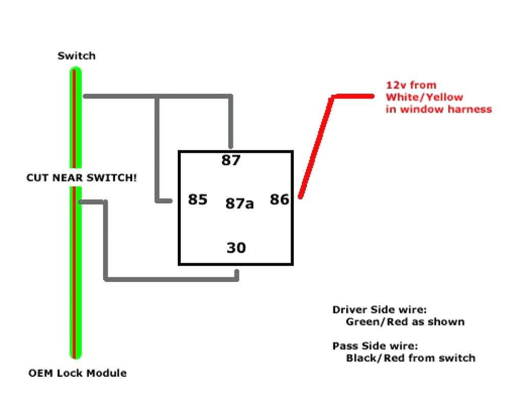
The wiring diagram for the Bosch relay 0332 provides a clear overview of how the relay should be connected to the electrical system. It shows the different terminals on the relay, as well as the connections to other components. The diagram typically includes labels for each terminal, indicating its function and the wire color that should be connected to it.
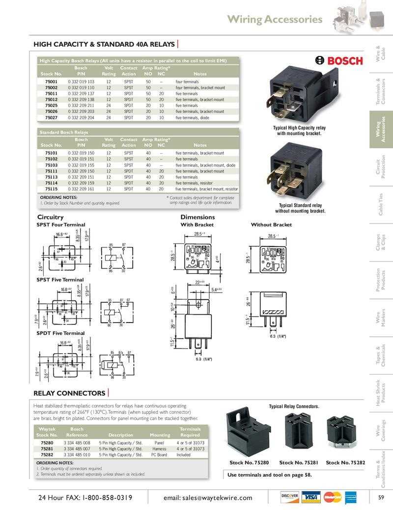
One important aspect of the wiring diagram is the pinout of the relay. This indicates which terminal should be connected to the power source, the load, and the control signal. In the case of the Bosch relay 0332, it has five terminals: two for the control signal, two for the load, and one for the power source. The wiring diagram will show the specific pin numbers for each terminal.
Depending on the application, the wiring diagram may also include additional components, such as diodes or resistors, that are necessary for proper functioning of the relay. These components are typically indicated with symbols and their values may be specified in a separate table.
Overall, the wiring diagram for the Bosch relay 0332 provides a comprehensive overview of how the relay should be connected in an electrical system. It is a valuable resource for installation, troubleshooting, and understanding the functionality of the relay.
Understanding the Pinout
The Bosch relay 0332 is a commonly used automotive relay that is designed to handle high current loads. The relay has five pins, each serving a specific purpose in the electrical circuit. Understanding the pinout of the relay is essential for properly wiring and utilizing its functionality.
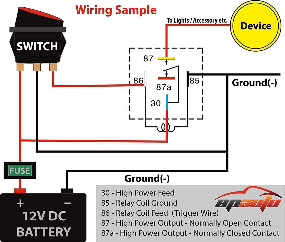
Pin 30:
-
Description: This pin is the common contact, also known as the NC (normally closed) contact. It is typically used when the relay is not energized, providing a closed circuit connection. When the relay receives power, this contact opens, breaking the circuit.
Pin 85:
-
Description: Pin 85 is the coil ground terminal. It connects to the ground or negative side of the power source, completing the circuit and allowing the relay to activate.
Pin 86:
-
Description: This pin is the coil positive terminal. It receives power from the power source, typically through a switch or control device, and energizes the relay coil, causing the contacts to change state.
Pin 87:
-
Description: Pin 87 is the normally open (NO) contact. When the relay is energized, this contact closes, allowing current to flow through the circuit. It is commonly used to control high-current devices such as headlights, fans, or pumps.
Pin 87a:
-
Description: This pin is the normally closed (NC) contact. When the relay is energized, this contact opens, breaking the circuit. It is often used in applications where a fail-safe operation is desired, such as controlling the fuel pump in an emergency shutdown scenario.
In summary, understanding the pinout of the Bosch relay 0332 is crucial for correctly connecting it to an electrical circuit. Each pin serves a specific function, such as providing a normally closed or normally open contact, completing the circuit, or activating the relay coil. Proper wiring and utilization of the relay will ensure efficient and reliable operation of the connected devices.
Step-by-Step Installation Guide for Bosch Relay 0332
When it comes to wiring a Bosch relay 0332, it’s important to have a clear understanding of the necessary steps to ensure a successful installation. This step-by-step guide will walk you through the process, highlighting key points and considerations along the way.
Step 1: Gather the necessary materials
Before starting the installation, make sure you have all the required materials at hand. This includes the Bosch relay 0332, appropriate wiring, wire connectors, a relay socket (if necessary), and any additional components specific to your application.
Step 2: Understand the relay pinout
Take a close look at the wiring diagram or pinout of the Bosch relay 0332. Familiarize yourself with the different pins and their functions. This will help you properly connect the relay to your electrical system later on.
Step 3: Identify the power source
Determine the power source that will be supplying the relay. This could be a battery or a separate power supply. Make sure the power source is able to handle the current requirements of the relay and the load that will be controlled by it.
Step 4: Connect the power source
Connect the positive (usually labeled as 30) and negative (labeled as 31) terminals of the power source to the corresponding pins on the relay. Use appropriate wire connectors to ensure a secure and reliable connection.
Step 5: Connect the load
Identify the load that will be controlled by the relay and determine the appropriate pin for connecting it. This could be a device, such as a fan or a light, or another circuit that needs to be activated or deactivated based on the relay’s operation. Connect the load to the designated pin on the relay using suitable wiring and connectors.
Step 6: Connect the control signal
Determine the source of the control signal that will activate or deactivate the relay. This could be a switch, a sensor, or another electronic component. Connect the control signal to the designated pin on the relay using appropriate wiring and connectors.
Step 7: Test the installation
Double-check all the connections and make sure everything is properly secured. Once satisfied, apply power to the system and test the relay’s operation. Verify that the load is being activated or deactivated correctly based on the control signal.
Step 8: Finalize the installation
Once you have confirmed that the relay is functioning as intended, finalize the installation by securing all the wiring and components in their proper places. Use cable ties or other appropriate methods to organize and protect the wiring.
Following this step-by-step installation guide will help you successfully wire a Bosch relay 0332 and ensure its reliable operation in your electrical system. Remember to always consult the manufacturer’s instructions and guidelines for specific details related to your application.
Troubleshooting and Common Issues
When wiring a Bosch relay 0332, it is important to ensure that everything is connected correctly in order to avoid any issues or malfunctions. However, if you encounter problems, here are some common issues and troubleshooting steps to consider:
1. Relay not working when powered
– Check the power source to ensure it is delivering the correct voltage and that it is properly connected to the relay.
– Inspect the relay connections to ensure they are secure and properly inserted into the relay terminals.
– Verify that the relay coil is receiving the necessary power by checking the voltage across the coil terminals.
2. Relay not switching on or off

– Check the wiring connections to the relay coil and load to ensure they are properly connected and secure.
– Make sure that the control signal (e.g., from a switch or sensor) is reaching the relay coil by checking the voltage across the coil terminals.
– If the control signal is present but the relay is not switching, the relay may be defective and will need to be replaced.
3. Electrical components overheating or melting
– Ensure that all wires and terminals are correctly sized and properly rated for the load being switched.
– Check for any loose or corroded connections, which can cause resistance and generate heat.
– If the load being switched by the relay is too high, consider using a higher-rated relay or adding additional relays in parallel.
4. Intermittent relay operation
– Check all wiring connections for any signs of damage, loose connections, or corrosion.
– Inspect the relay terminals for any signs of overheating or melting, which can indicate a poor connection.
– If the relay is exposed to excessive vibration or temperature fluctuations, consider adding additional support or insulation to ensure stable operation.
By troubleshooting and addressing these common issues, you can ensure the proper functioning of the Bosch relay 0332 in your wiring system.