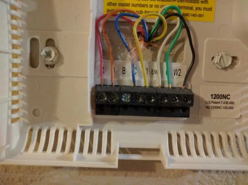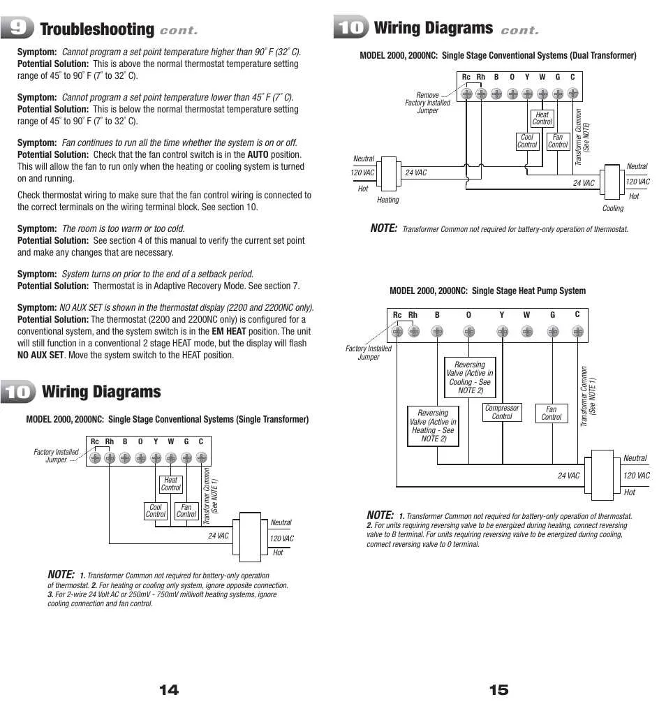
When setting up your temperature control unit, the first step is ensuring the correct connection of the various terminals. A clear layout of the components will guide you through linking the heating and cooling systems efficiently. Pay close attention to the power source and its correct routing to avoid any issues with functionality.
Ensure proper connection of the terminals to avoid any interference or faulty readings. Double-check the wiring for the control system to confirm that each wire is securely placed in its designated slot. Incorrect placement can result in poor performance or even equipment damage.
To avoid confusion, label each wire before installation. This step will help you during future maintenance or troubleshooting. The use of high-quality wires that match the specifications of your system is crucial for optimal operation.
Proper Connection Guide for Heating Control System
Ensure you connect each terminal to the corresponding wire from the control unit. Start by identifying the power source and verify that the system is completely powered off before proceeding.
The R terminal should be linked to the red wire, which provides the primary power to the system. This is essential for activating the system.
Next, connect the W terminal to the white wire, which handles heating signals. This wire directs the signal for activating the heating function.
The C terminal requires the connection of a common wire, typically colored blue or black, to complete the circuit. This wire is crucial for maintaining a continuous power flow and ensures proper system functionality.
For cooling functionality, the Y terminal should be connected to the wire that controls cooling, typically green or yellow. This step is necessary for regulating temperature reduction when needed.
Finally, make sure that the G terminal is connected to the fan wire, which is generally green. This ensures the ventilation system is properly integrated into the setup.
Double-check the connections before powering the system back on to avoid any malfunction.
Understanding the Wiring Terminals
To ensure proper installation, identify the terminal labels before proceeding with the connections. This will prevent miswiring and malfunctioning of the system. Pay close attention to the following key terminals:
- R: Typically for the 24V power input, providing the main power source to the device.
- C: This terminal is used to complete the power circuit, ensuring proper function of the system.
- Y: Controls the cooling system, usually connected to the air conditioning unit.
- W: Used for heating, connects to the heating unit in the system.
- G: Controls the fan, ensuring proper airflow within the system.
- O/B: This terminal is used to switch between heating and cooling, depending on the system’s needs.
Proper connection to each terminal is essential for the system to respond correctly to temperature adjustments. Always double-check that each wire is securely attached to its respective terminal.
In systems that support heat pumps, be sure to correctly identify the O/B terminal, as its function can vary depending on the setup.
How to Connect the Wires Correctly to Avoid Common Issues
Ensure proper connection of each wire to its designated terminal to prevent malfunction. Incorrect placements, such as connecting the wrong wires to heating or cooling terminals, can lead to system failure or erratic behavior. Double-check the color codes and labeling of each wire to confirm their respective positions.
Verify secure wire connections to avoid poor contact that may result in intermittent functionality. Use high-quality connectors and ensure the wires are firmly inserted into their terminals. Loose or corroded connections often lead to voltage issues, making the system unreliable.
Use a multimeter to test the system after making the connections. This step ensures the proper electrical flow and prevents short circuits. Always check voltage levels before powering up the unit to confirm the integrity of your setup.
Follow manufacturer guidelines for specific instructions on wire placement to avoid damaging sensitive components. Even if there are no visible issues, improper connections can still affect performance and cause long-term damage.
Step-by-Step Guide to Installing a Heating and Cooling Control System

Begin by identifying the terminals on the control unit. You’ll typically find labels such as “R”, “C”, “Y”, “W”, and “O/B.” Make sure to double-check these labels before proceeding to connect the corresponding wires from your heating and cooling system.
Start with the “R” terminal, which provides the power to the system. Connect the red wire from the power supply to this terminal. Ensure the connection is tight and secure to prevent any disruptions in the power flow.
Next, connect the white wire to the “W” terminal for the heating function. This wire controls the heat cycle, so it must be linked directly to the system’s heating control panel.
For the cooling component, attach the yellow wire to the “Y” terminal. This wire triggers the cooling mechanism when the temperature rises above the desired set point.
If your system uses a heat pump, you’ll need to connect the orange wire to the “O/B” terminal. This wire controls the changeover valve that switches between heating and cooling modes.
Lastly, connect the blue or black wire to the “C” terminal. This is the common wire that completes the circuit, allowing the system to operate properly.
After all wires are securely in place, check the connections once more before turning the system’s power back on. Test the functionality by adjusting the temperature settings and verifying that both heating and cooling functions are responsive.