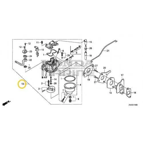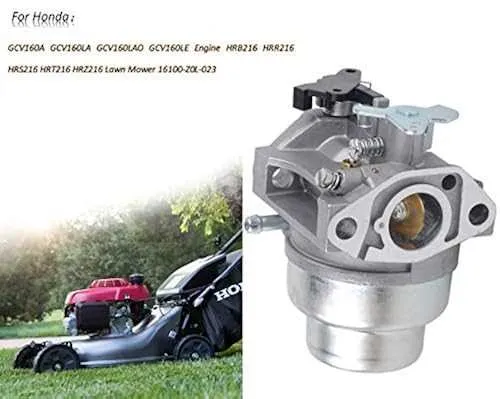
For precise maintenance and troubleshooting of a walk-behind grass cutter, referencing a detailed schematic of the fuel delivery assembly is crucial. Understanding the layout of the mixing chamber, throttle linkage, and adjustment screws helps optimize performance and resolve common issues such as stalling or poor acceleration.
Familiarize yourself with the key parts: float bowl, jets, needle valve, and choke plate. Each element influences fuel flow and air mixture, directly impacting engine efficiency. Proper alignment and clean passages prevent flooding and ensure smooth ignition.
Regular inspection guided by an accurate visual representation simplifies identification of wear or blockages. When cleaning or replacing components, this reference minimizes trial-and-error, reducing downtime and prolonging equipment lifespan.
Engine Fuel System Breakdown

To properly service the fuel delivery unit on this type of garden equipment, begin by identifying the main components: the throttle lever, choke plate, float chamber, needle valve, and main jet. The throttle lever controls air intake, while the choke plate restricts airflow to enrich the fuel mixture during startup.
The float chamber regulates fuel flow using a buoyant mechanism connected to the needle valve, preventing overflow. Inspect the needle valve for wear or debris, as this often causes flooding or fuel starvation. The main jet meters the fuel entering the combustion chamber; ensure it is clean and unobstructed for optimal performance.
During disassembly, note the gasket placement between the fuel bowl and body to avoid leaks after reassembly. Use compressed air to clear all small passages, especially around the idle circuit. Adjust the idle screw to achieve a smooth engine run at low speed. Regular maintenance of these components enhances fuel efficiency and prevents stalling.
Identifying Key Components in Engine Throttle Assembly Illustration

Main body serves as the foundation, housing internal pathways for fuel and air mixture. Focus first on this part to understand overall layout.
Float chamber controls fuel level; locating it helps diagnose flooding or fuel starvation issues. It’s typically a small reservoir attached to the side of the assembly.
Needle valve regulates fuel flow into the float bowl; ensure it aligns properly with the float mechanism for correct operation.
Main jet determines fuel delivery rate; its size and position directly affect engine performance under load.
Throttle plate controls airflow into the engine, linked to the throttle lever. Identifying this part clarifies speed adjustment functionality.
Choke valve enriches the fuel mixture during cold starts; note its placement near the air intake path for effective cold weather operation.
Idle screw adjusts fuel-air ratio at low speeds; locating it allows precise tuning of engine idling.
Venturi passage creates pressure differential to draw fuel into airflow; recognizing this narrow section is essential for understanding mixture formation.
Fuel inlet fitting connects the fuel line to the assembly; ensure its seal is intact to prevent leaks.
Step-by-Step Guide to Adjusting the Fuel Mixer Using the Illustration
Start by locating the idle speed screw and the mixture screws on the component. These control engine idling and fuel-air balance. Follow these precise steps:
- Warm up the engine for 3 to 5 minutes to reach normal operating temperature.
- Turn both mixture adjustment screws clockwise gently until they lightly seat; avoid forcing them.
- Back each screw out exactly 1¼ turns to set the baseline for fine-tuning.
- Adjust the idle speed screw to achieve approximately 1200 RPM; use a tachometer for accuracy.
- Slowly turn the low-speed mixture screw clockwise until the engine stumbles, then counterclockwise to the highest smooth RPM point.
- Repeat for the high-speed mixture screw, ensuring peak engine response without hesitation or bogging.
- Re-check idle speed and readjust the idle screw to maintain consistent engine RPM.
- Inspect the throttle linkage for smooth operation and adjust if needed to prevent stalling or over-revving.
- Test engine response under load; if surging occurs, slightly lean the mixture by turning screws counterclockwise in 1/8-turn increments.
Always reference the component’s schematic to identify correct screw positions and ensure proper adjustment sequence. Precise tuning improves performance, fuel efficiency, and reduces emissions.
Troubleshooting Common Fuel System Issues with Lawn Equipment Diagram
Check the fuel intake valve first if the engine struggles to start or stalls frequently. Deposits or debris can block proper fuel flow; clean the valve and replace the gasket if cracked or worn.
Inspect the float mechanism to ensure it moves freely and maintains correct fuel levels in the bowl. A stuck float can cause flooding or fuel starvation. Adjust float height according to the schematic specifications.
Examine the jets and passages for clogging caused by varnish or dirt buildup. Use compressed air or carburetor cleaner to clear obstructions, ensuring smooth fuel delivery at all throttle settings.
Verify the choke plate operation. A malfunctioning choke can lead to hard starts or rough idling. Ensure the linkage moves without resistance and closes completely during cold starts, as shown in the technical drawing.
Check the diaphragm and seals for cracks or brittleness, which impair proper fuel metering. Replace any damaged components following the parts layout to restore efficient fuel regulation.
Tighten mounting screws to prevent air leaks around the assembly base. Air infiltration can disrupt the air-fuel ratio, causing poor engine performance. Confirm tightness using the exploded view for proper torque points.