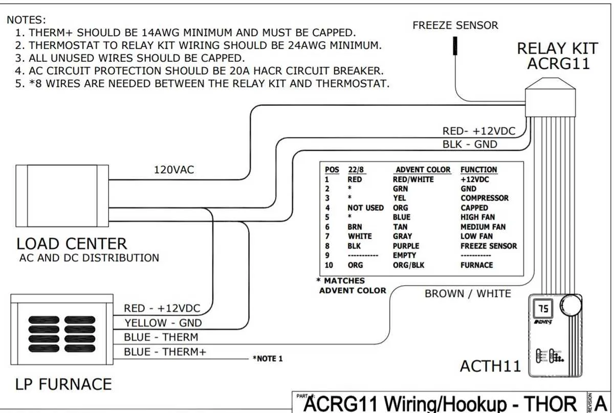
Ensure all connections are made securely between the control unit and the temperature regulation components. Proper placement of wires is crucial to maintaining system functionality and preventing damage to sensitive equipment. Start by connecting the power supply terminals to the main control board, ensuring polarity is correct. This is key for the system to operate reliably.
Check for compatibility between your system’s power requirements and the wiring setup. Using wires of the appropriate gauge and ensuring proper insulation will protect against short circuits or overheating. If your setup involves a relay, confirm that the control circuit is separated from the power circuit to avoid interference.
Test the system after installation by verifying voltage at each terminal point, making sure each connection is receiving the correct input. It’s also recommended to test the control board for any signs of malfunction, such as incorrect readings or unresponsive settings. This step ensures the unit is ready for continuous use without potential failures.
Wiring Setup for Temperature Control System
For proper installation, ensure to connect the wires to the terminals based on their respective functions. Here’s a concise guide to assist you:
- Red wire: Connect to the power source terminal, typically labeled as “R” or “VCC.” This wire provides constant voltage.
- White wire: This is the heating control, typically wired to the terminal marked “W.” It activates the heating element when needed.
- Green wire: Often used for grounding, it should be connected to the terminal marked “G” to ensure proper safety.
- Yellow wire: If present, connect it to the cooling control terminal, usually marked “Y.” It controls the cooling system.
- Blue wire: Used in some systems for auxiliary heating, this connects to the terminal marked “C” for continuous current supply.
Verify that each wire is securely fastened to prevent short circuits or malfunction. Double-check the wiring layout against your unit’s manual for any system-specific requirements.
Before powering the unit, ensure all connections are insulated properly and that there are no exposed wires. This step is crucial for safety and efficiency.
Identifying Key Wires for Connection Setup
Ensure you locate the power input wire first. This is typically connected to the main electrical source and should be clearly marked. It is vital for proper functioning of the system.
The signal wire is often used to send commands to activate heating or cooling. It is usually a single, color-coded wire distinct from the others. Check for a common color scheme, such as red for heat or green for cooling.
The neutral wire should be connected to the system’s ground. This wire is essential for completing the circuit and preventing electrical malfunctions. It often appears white or blue.
Lastly, identify the auxiliary control wire if your system requires it. This wire may carry additional signals, such as fan control or temperature regulation adjustments. Its color may vary depending on the model.
Step-by-Step Installation Process for Climate Control Device
Begin by turning off all power sources to prevent any electrical accidents. Locate the control unit’s connection panel, ensuring it is easily accessible for proper installation.
1. Prepare the Connections: Strip the wires to expose the necessary length of copper to make secure connections. Be careful not to damage the wires during this process. You’ll need to connect the power, ground, and signal wires to their corresponding terminals.
2. Attach Power Wires: Secure the live and neutral power wires to their designated terminals. Double-check that the connections are tight and that no copper is exposed outside the terminals, as this could lead to short circuits.
3. Grounding: Proper grounding is crucial. Connect the ground wire to the ground terminal. This step ensures safe operation by preventing electrical surges or faults.
4. Connect Control Wires: For temperature regulation, connect the control signal wires to the designated terminals. These wires will communicate with the device to maintain the set temperature. Ensure that each wire is placed in its correct slot to avoid malfunctions.
5. Secure the Wiring: Once all connections are in place, secure the wires with cable ties to prevent any movement or strain. This will keep the wires organized and reduce the risk of accidental disconnections or damage.
6. Testing: Power up the system and test the device. Ensure it responds correctly to the temperature adjustments and operates smoothly. If there are issues, check each connection carefully for loose or improper wiring.
Common Connection Issues and Troubleshooting Tips
Check power supply: Ensure that the power source is functioning properly. Use a multimeter to verify that the circuit provides the correct voltage. A faulty power supply is one of the most frequent problems.
Inspect terminals and connections: Loose or corroded terminals can lead to poor conductivity and erratic performance. Examine all connections carefully and clean them using a wire brush or contact cleaner to restore proper contact.
Examine control board: If your system isn’t responding, inspect the control board for visible damage. Look for signs of burnt components or broken solder joints. If any issues are found, replacing the board may be necessary.
Wiring integrity: Look for frayed, cracked, or damaged wires along the entire circuit. Even small cuts can disrupt signals and cause malfunction. Repair or replace any damaged sections immediately.
Faulty sensors: Sensors that are not reading correctly can cause inaccurate temperature regulation. Test sensors using a multimeter to ensure proper operation. If the sensor is malfunctioning, it will need to be replaced.
Ensure proper grounding: A poor ground connection can cause the system to misbehave. Check the ground connections to ensure they are secure and free of corrosion.
Test relays: If the unit is not activating as expected, faulty relays could be the cause. Test each relay for continuity and replace if necessary to restore full functionality.