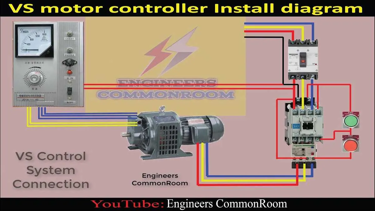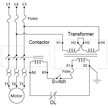
Ensure precise matching of voltage and current specifications to avoid damage and ensure efficiency. When assembling the power network for machinery, focus on the correct sequence of phases and grounding to enhance safety and performance. It’s crucial to verify that all components are rated appropriately for the power input to avoid unnecessary strain on the system.
When connecting the electrical system to a mechanical device, prioritize the use of reliable connectors that match the gauge of the wires. Undersized or incompatible connectors may lead to overheating or electrical faults. Be cautious when dealing with high-power systems, as even minor errors in wiring can cause short circuits or malfunction.
For multi-phase equipment, ensure that each phase is properly balanced and connected to the right terminal. Uneven phase distribution can result in reduced efficiency and potential system failures. Double-check the entire setup with a multimeter before powering up to guarantee proper continuity and voltage distribution.
Tip: Always use proper insulation and protective devices to shield sensitive components from surges or accidental short circuits. Regularly inspect connections to avoid deterioration due to wear or exposure to environmental factors.
Electrical Setup for Electric Machines
Ensure proper alignment of each terminal before making any linkages. Correct placement of wires plays a key role in performance and safety. Follow these steps for effective setup:
- Start by identifying the phases of the system: single-phase or three-phase. This determines the components required for assembly.
- Connect the supply lines to the correct input terminals, making sure the voltage matches the machine’s requirements.
- For three-phase configurations, link the corresponding phases to prevent imbalance and potential damage to components.
- Grounding is mandatory. Secure a reliable grounding point to prevent electrical hazards.
- Use insulated cables for high-voltage connections to prevent accidental short circuits.
Always verify the current rating and resistance of each part to ensure compatibility. Regular inspections and maintenance checks will keep the system running smoothly.
- Check insulation regularly to avoid wear and tear.
- Ensure all joints are tightly secured to avoid power loss and overheating.
- Use high-quality terminals to improve durability and conductivity.
Understanding the Basic Components of a Motor Wiring Diagram
The first essential element is the power supply, often represented by a pair of lines showing where the electricity enters the system. These lines are typically marked with L (live) and N (neutral) to indicate their respective functions. Make sure to correctly identify these before making any adjustments to avoid short circuits or incorrect polarity.
Next, the control switches allow you to manage the on/off state of the device. They are often illustrated as a pair of terminals where one side is connected to the live wire, and the other side leads to the electrical device. Switches may also include auxiliary contacts that monitor or adjust the status based on specific conditions.
For protection, fuses or circuit breakers are integrated into the setup. These safety components break the circuit if the current exceeds a certain threshold, preventing overheating or fire hazards. They are marked with their ampere rating, which defines the safe operational limit.
The starter coil is another key part of the system, generally depicted as a coil symbol. This component energizes the primary circuit when the system is switched on. Its role is crucial in creating the magnetic field necessary for activating the electrical apparatus.
In addition, the relay often appears as a switch with a coil. It operates automatically based on the current supplied to it, controlling the flow of electricity to various parts. Relays are often used for switching between different operational modes or to isolate different circuit sections for safety or efficiency.
Finally, grounding points are vital for safety. These connections are usually represented with a special symbol, and their purpose is to direct any stray electrical currents safely to the earth, minimizing the risk of electrical shock or fire. Ensure that grounding is solid and continuous across the setup to prevent potential issues.
Step-by-Step Guide to Wiring a Motor for Single-Phase Operation

1. Begin by identifying the two leads from the power supply: neutral and live. Ensure you have the correct voltage rating for the setup.
2. Connect the neutral wire to the motor’s neutral terminal. This is often marked clearly on the motor’s terminal block.
3. Attach the live wire to the first terminal on the motor, which is designated for power input. Ensure this connection is secure to avoid any loose contacts.
4. For the second terminal, connect a capacitor that matches the motor’s specifications. This component is necessary for starting the motor with single-phase power.
5. Use appropriate clamps or screws to ensure all connections are tight and stable. Loose connections can lead to overheating or malfunction.
6. Install a protective fuse or circuit breaker to safeguard the system against overloads. Choose a fuse rating that corresponds to the motor’s maximum current requirement.
7. Finally, check the motor’s rotation direction by briefly powering it up. If it rotates in the wrong direction, reverse the live and neutral connections.
Troubleshooting Common Electrical Issues
Verify the power supply to ensure it’s delivering the correct voltage for the equipment. Check both ends of the cable to confirm that no loose or damaged contacts are preventing proper flow. Inspect the fuse or circuit breaker for any signs of overload or malfunction; replace if necessary.
If the device is not starting, inspect the internal switch for faults, as it may fail to engage correctly. Use a multimeter to test continuity in the circuit and identify any breaks. Examine any connectors or terminals for corrosion that could interfere with a solid connection.
For improper performance, assess the ground connections to ensure they are secure and without resistance. If overheating occurs, verify that the load is within acceptable limits and there are no short circuits in the system.
If a humming sound or irregular operation is heard, inspect the capacitors for signs of wear or damage. Testing them with a capacitance meter can help detect faulty components that may need replacing.
Finally, review any control systems or relays for malfunction. An improperly functioning relay may prevent the entire system from running as intended. Ensure that all control settings are configured correctly to avoid issues in the electrical path.