For anyone working on a six-cylinder powertrain, it’s crucial to familiarize yourself with the component layout and their respective connections. The V6 configuration offers a balance between performance and efficiency, and understanding its internal setup is essential for any maintenance or modification task.
Focus first on the positioning of cylinders and how they are arranged within the block. The distinctive V-shape layout impacts the timing and firing order, which is crucial for smooth operation. Pay attention to how the intake and exhaust systems are routed, as well as the placement of various sensors that contribute to fuel management and emissions control.
Take particular note of the valvetrain system, which is integral to engine performance. Understanding the relationship between the camshaft, lifters, push rods, and rocker arms is vital for diagnosing issues such as misfires or power loss. Identifying each component’s location and its function will provide a clearer picture when troubleshooting or upgrading specific parts.
Finally, ensure that you understand the cooling system layout, as proper fluid flow is essential for maintaining optimal operating temperatures. The thermostat, water pump, and radiator must all work in tandem to prevent overheating and prolong the life of the motor.
Detailed Overview of the V6 Powerplant Configuration

For optimal performance, pay close attention to the cylinder arrangement and firing order of the six-cylinder setup. The key components to examine include the intake manifold, camshaft, and timing chain. Ensure that the valve lifters and rocker arms are correctly aligned to avoid irregularities in valve operation. The fuel injection system should be inspected for proper spray patterns and pressure regulation.
The cooling system, including the water pump and radiator, must be properly sized to manage heat dissipation across the block. Maintain accurate ignition timing to prevent knocking and enhance fuel efficiency. Be aware of the crankshaft’s position and check for any bearing wear during routine maintenance to prevent unwanted vibrations.
When servicing, always confirm the alignment of the accessory drive components, such as the alternator and power steering pump, as misalignment can lead to belt wear and underperformance. A well-maintained exhaust manifold and catalytic converter ensure smooth airflow and reduced emissions.
Ensure that the vacuum lines remain intact and free from leaks to guarantee optimal operation of the fuel management system and emissions control. Monitoring the oil pressure is crucial for maintaining lubrication and preventing internal damage to the block and rotating assembly.
Key Components of the V6 Powerplant and Their Functions

Understanding the core parts of the V6 system is crucial for effective maintenance and troubleshooting. Below are the essential components and their roles:
- Crankshaft: Converts linear motion of pistons into rotational power, driving the vehicle’s transmission system.
- Pistons: Move up and down inside the cylinders, compressing the fuel-air mixture, and transferring force to the crankshaft.
- Cylinder Heads: House the intake and exhaust valves and are critical in controlling the flow of air and fuel into the combustion chamber.
- Valves: Control the intake of the air-fuel mixture and the exhaust of combustion gases, regulated by the camshaft.
- Camshaft: Controls the opening and closing of valves, dictating the timing of fuel intake and exhaust release.
- Timing Chain/Belt: Synchronizes the rotation of the crankshaft and camshaft, ensuring proper valve timing for each piston stroke.
- Fuel Injectors: Deliver a precise amount of fuel into each cylinder based on engine demand, contributing to fuel efficiency and performance.
- Ignition System: Sparks the air-fuel mixture at the optimal moment, facilitating combustion. It includes the spark plugs, coils, and related sensors.
- Intake Manifold: Distributes the air-fuel mixture evenly to all cylinders, ensuring efficient combustion and consistent performance.
- Exhaust Manifold: Collects exhaust gases from each cylinder and channels them to the exhaust system for further processing.
- Oil Pump: Circulates engine oil throughout the system to lubricate moving parts, reducing friction and preventing overheating.
- Water Pump: Facilitates coolant flow, regulating temperature by ensuring proper heat exchange in the system.
- Alternator: Generates electrical power to recharge the battery and support electrical systems while the engine is running.
Each of these parts plays a vital role in optimizing power output, fuel efficiency, and overall reliability. Regular inspection and maintenance of these components can prevent costly repairs and improve vehicle longevity.
How to Read and Interpret the Chevy 4.3 V6 Engine Diagram
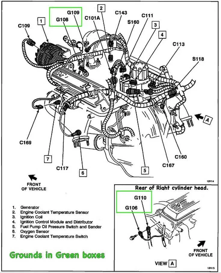
Start by locating the intake manifold at the top center of the layout–this component distributes the air-fuel mixture to the cylinders. Identify the fuel injectors next; they’re typically marked near the runners and correspond to each cylinder port. Match the injector labels with the cylinder numbering sequence: 1-3-5 on the driver’s side, 2-4-6 on the passenger side.
Trace the ignition system connections from the distributor or coil packs. Confirm the correct firing order: 1-6-5-4-3-2. Verify wire routing by following each line from the ignition control to the spark plug sockets, ensuring proper sequence and placement. Misrouting here causes misfiring or rough idling.
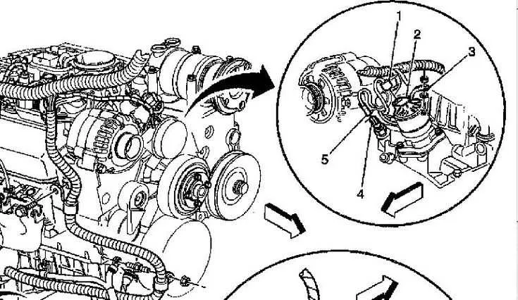
Locate the crankshaft sensor near the harmonic balancer or rear of the block–its signal input is crucial for timing. Nearby, spot the camshaft position sensor mounted in the front cover or distributor base. These signals are used by the control module for spark and fuel synchronization.
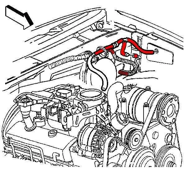
Check the vacuum lines and their routing–ensure each hose is correctly labeled and attached to its designated port, such as the EGR valve, PCV system, or brake booster. Misconnected lines lead to drivability issues or emission faults.
Observe coolant path lines: thermostat housing, radiator hoses, and bypass tubes. Confirm the coolant temperature sender location, usually near the thermostat outlet or cylinder head, and match it with the labeled sensor on the map.
Finish by reviewing all ground points and harness connectors. A missed ground or corroded connection can disable ignition or fuel delivery systems. Use the legend or key if available to decode wire colors and connector IDs accurately.
Troubleshooting Common Issues Using the Chevy 4.3 V6 Engine Diagram
Check ignition coil wiring first: Locate the coil connector on the schematic and confirm voltage presence with the key in the ON position. Absence of voltage typically points to a failed ignition switch or broken feed wire.
Inspect crankshaft position sensor (CKP) signal: Using the chart, trace the CKP leads back to the ECM. Use an oscilloscope to verify waveform. Flat or erratic output may indicate sensor failure or damaged wiring.
Test injector circuit continuity: Refer to the harness map to identify the correct pins. Apply a multimeter to each injector lead to check resistance. Deviations from the expected 11–14 ohms suggest a short or open circuit.
Validate ground connections: Ground points labeled G102 and G103 often cause intermittent misfires or hard starts. Ensure tight contact with bare metal and clean off any corrosion. Reference exact locations using the harness layout.
Analyze EGR valve control path: Using the layout, confirm that the vacuum solenoid receives signal from the control module. A missing 12V feed or no ground pulse indicates a failed driver circuit or broken wire.
Test mass airflow sensor voltage: Follow the schematic to identify the MAF power and signal wires. Key ON voltage at the signal wire should range between 0.5–1.5V at idle. Deviations may point to sensor fault or harness issue.
Inspect fuse panel connections: Examine all fuses related to powertrain circuits as mapped. A blown 10A or 15A fuse connected to ignition control or injectors will disable startup. Replace only after confirming root cause via circuit tracing.