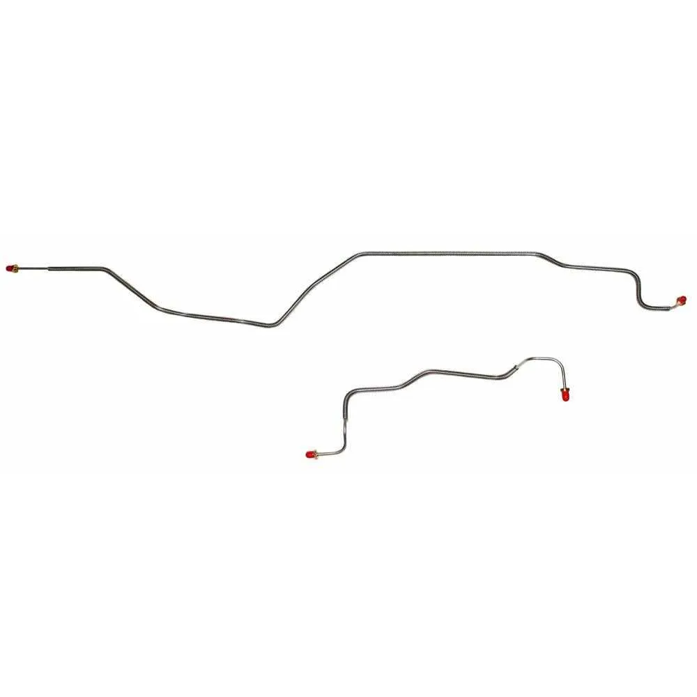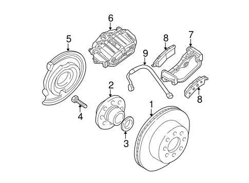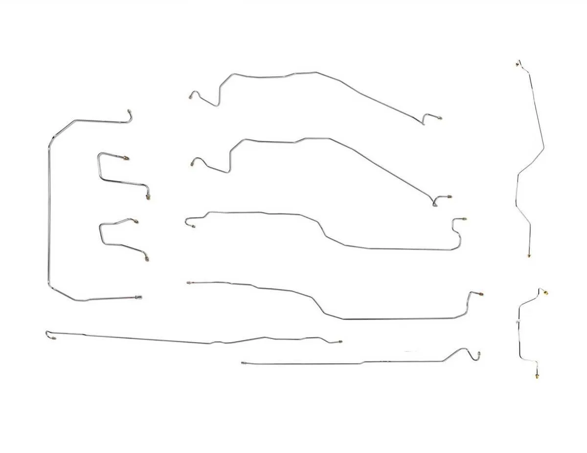
For accurate troubleshooting and maintenance of the hydraulic fluid pathways in your vehicle, refer to the detailed schematic of the entire system. This will ensure that you can pinpoint the exact location of any issues with fluid circulation or pressure build-up. Having a reliable visual reference will significantly simplify the repair process.
The fluid conduit routing in the 2004 model has specific paths and connections that must be followed during replacement or inspection. It is essential to identify each connection point between major components to avoid leaks or improper installations that can compromise performance. Understanding the placement of critical junctions, valves, and connectors is key to maintaining operational integrity.
Ensure you examine the fluid delivery channels from the master unit to the wheels for any signs of wear or corrosion. A comprehensive view of the entire structure will help you visualize the flow of hydraulic pressure and detect any irregularities that might arise. The use of high-quality replacement components is highly recommended to prevent future issues.
By referencing a well-documented schematic, you reduce the risk of costly errors and improve the efficiency of your repair efforts. Always cross-check with the manufacturer’s specifications to ensure correct alignment and pressure regulation across the entire hydraulic system.
Essential Overview of 2004 Vehicle Hydraulic System Setup

For accurate troubleshooting or modifications of the hydraulic fluid distribution system in a 2004 model, reference the layout for seamless routing of components. Start by identifying the primary conduits leading from the master cylinder to each wheel’s actuator. Ensure the connectors are tightly secured and free from corrosion.
Focus on the front-to-rear distribution: The front pipes typically split from the primary unit under the engine bay, running towards the wheel mechanisms. These conduits are often exposed to road conditions, so consider using heat-resistant and abrasion-resistant materials for replacements.
Rear sections: These lines run along the vehicle’s underside, passing through dedicated brackets. Check that these connections are free from kinks or wear that could lead to reduced performance or fluid leaks. Make sure to tighten all fittings securely and inspect for any signs of deterioration in rubber sections.
Ensure all unions and fittings are properly torqued according to manufacturer specs to prevent any fluid loss under pressure. Consider upgrading to stainless steel for added durability and longevity.
For detailed installation, use an up-to-date schematic to confirm exact measurements and angles of the tubes for a precise fitment. Always replace any damaged sections promptly to maintain optimal hydraulic system functionality.
Identifying Key Components in the Hydraulic System of the 04 Pickup
Master Cylinder: This is the central component that converts the force from the pedal into hydraulic pressure. If there’s a failure here, the entire system may lose functionality. Check for fluid leakage around the master cylinder and inspect the seals for any signs of wear.
Flexible Hoses: These hoses carry hydraulic fluid between key components. Inspect each one for cracks, bulges, or any damage. Replace any that show signs of degradation, as these can cause fluid loss and result in poor performance.
Hard Tubes: Rigid metal tubes deliver hydraulic fluid to the wheel assemblies. They are more durable but can corrode over time. Look for visible rust or dents along the length of the tubes, and ensure they are securely attached to the frame to avoid leaks.
Proportioning Valve: This component ensures the correct distribution of hydraulic pressure to the wheels. If it fails, one or more wheels may receive too much or too little pressure, causing uneven stopping power. Make sure it is correctly calibrated and functioning.
Wheel Cylinders: These are located at each wheel assembly and convert hydraulic pressure into mechanical force to engage the pads or shoes. Inspect for leaks, corrosion, and ensure that the cylinders are moving freely without obstruction.
Reservoir: The fluid reservoir holds the hydraulic fluid for the system. Always check the fluid level and top it off if necessary. If the level is consistently low, there may be a leak somewhere in the system.
Step-by-Step Guide to Replacing Damaged Brake Lines on the 04 Silverado
1. Begin by safely lifting the vehicle using a hydraulic jack and securing it with jack stands. Ensure the car is level and stable before proceeding.
2. Locate the damaged pipe. Inspect the entire length for cracks or corrosion, paying attention to connections and fittings at the corners and joints.
3. Use a wrench to loosen any fittings connected to the damaged section, ensuring you have a bucket or container to catch any residual fluid. Be prepared for leakage when removing components.
4. Once the affected segment is detached, measure the exact length required for the replacement. Note the diameter and thread size to ensure compatibility with your new part.
5. Cut the new tubing to the correct length using a tubing cutter. Make sure the cut is clean and straight to avoid leaks at the connections.
6. Bend the new pipe gently into shape, using a pipe bender to avoid sharp angles. Ensure the new tubing follows the same routing as the original one to prevent interference with other vehicle components.
7. Attach the new pipe to the fittings. Hand-tighten the connections before using a wrench to secure them. Take care not to overtighten, as this could damage the threads or deform the tubing.
8. Once secured, bleed the system by starting at the farthest wheel from the master cylinder and working your way to the nearest. This will remove any air trapped in the system, ensuring proper fluid flow.
9. Check for any leaks by applying pressure and inspecting the connections. Tighten any fittings if necessary.
10. Lower the vehicle carefully and test drive to confirm that the system is functioning correctly without any signs of fluid loss or abnormal performance.
Common Issues with Brake System Layouts in the 04 Model and How to Fix Them

If you’re experiencing problems with fluid distribution or pressure loss in the braking system, it’s crucial to check the setup thoroughly. Here are the common issues and solutions:
- Incorrect Routing of Tubing: Ensure the pipes are not touching hot engine components or sharp edges, as this can cause wear and eventual failure. Use proper clamps and routing paths to keep everything secure and in place.
- Leaks at Connections: Leaks often occur at junctions or threaded fittings. Tighten connections properly, and use sealing tape or fluid-compatible sealant to prevent further leakage. If the seal is damaged, replace the washers or O-rings.
- Corrosion: Over time, metal components can corrode, leading to blockages or weakened sections. Inspect the tubing for signs of rust and replace any affected sections. Applying anti-corrosion spray can help extend the life of the system.
- Clogged Tubes: Dirt and debris can build up in the pipes, obstructing fluid flow. Regular cleaning and maintenance can prevent this. If a clog is detected, replace the affected section.
- Improper Component Sizing: Incorrect diameter or length of tubing can cause issues with pressure regulation. Always double-check the specifications for replacement parts before installation.
Regular inspection and maintenance of the entire setup are essential to ensure safe and reliable operation. If you’re unsure about the condition of any components, it’s best to consult a professional for a thorough inspection and replacement as needed.