
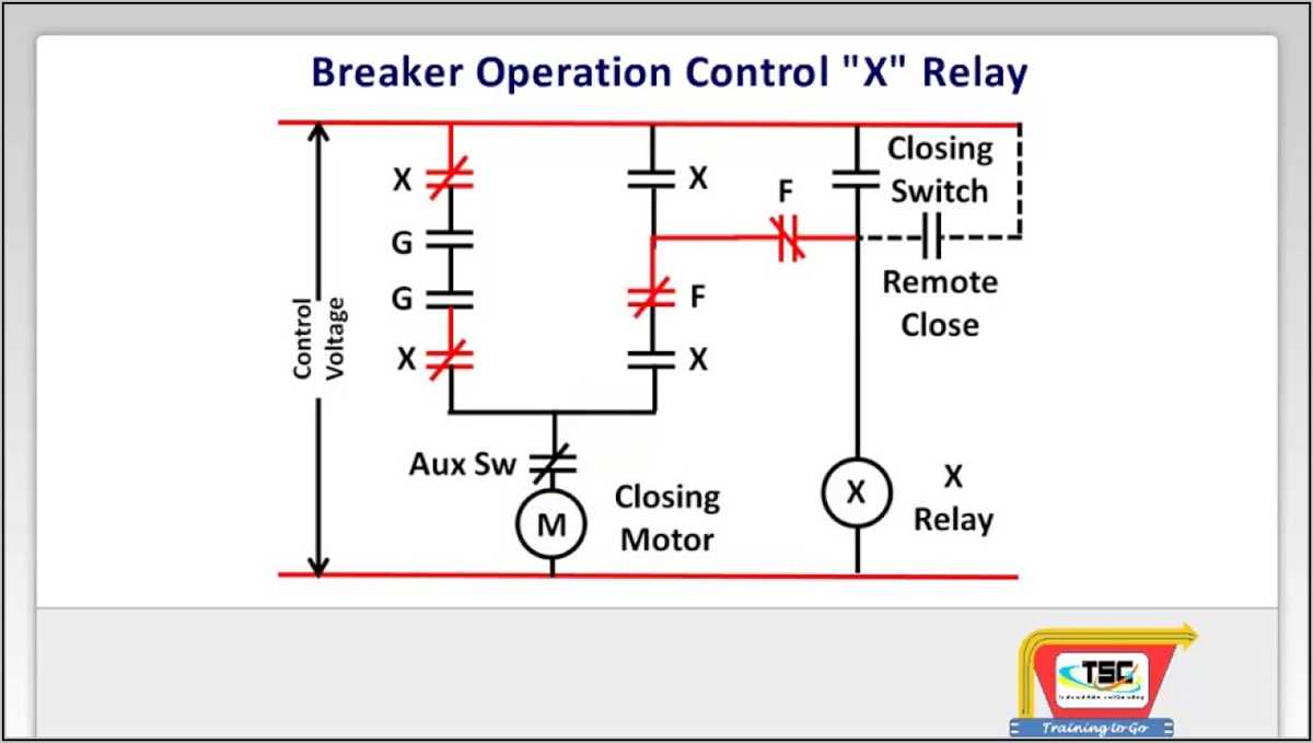
A circuit breaker schematic is a graphical representation of the electrical connections and components in a circuit breaker. It shows how the different parts of the circuit breaker are connected and functions.
The schematic typically includes symbols for the circuit breaker, contacts, coils, trip unit, and other elements. It also shows the connections between these components and how they interact with each other. The circuit breaker schematic helps engineers and technicians understand the working of the circuit breaker and troubleshoot any issues that may arise.
The circuit breaker schematic is an essential tool for designing, installing, operating, and maintaining electrical systems. It provides a clear visual representation of the circuit breaker and helps ensure that the correct connections are made during installation. It also aids in troubleshooting by allowing technicians to quickly identify faulty components or connections.
In addition to its practical uses, the circuit breaker schematic can also be used for educational purposes. It helps students and trainees understand the different components and their functions in a circuit breaker. It provides a visual aid that enhances their learning experience and helps them grasp complex electrical concepts more easily.
Circuit Breaker Schematic: Definition and Purpose
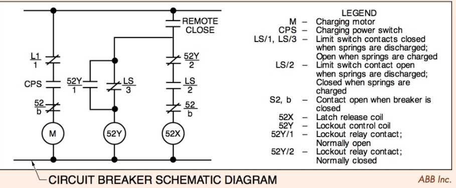
A circuit breaker schematic refers to a diagram or drawing that illustrates the various components and connections of an electrical circuit breaker. It provides a detailed representation of how the circuit breaker functions and helps in understanding its overall design and operation. The schematic diagram includes symbols and lines that represent different elements, such as switches, fuses, coils, contacts, and other components that make up the circuit breaker system.
The purpose of a circuit breaker schematic is to provide a visual representation of the circuit breaker’s internal structure and its interaction with the electrical system. It serves as a guide for technicians and engineers in understanding the circuit breaker’s functionality, troubleshooting any issues, and making necessary modifications or repairs. The schematic diagram also helps in designing and building new circuit breakers, as it provides a blueprint for the construction of the device.
The circuit breaker schematic typically includes information about the different types of circuit breakers, such as thermal, magnetic, and hybrid circuit breakers, along with their specific ratings and trip characteristics. It also shows the various connections, such as the line and load terminals, as well as the control wiring that allows the circuit breaker to be operated manually or automatically. Additionally, the schematic may depict the presence of auxiliary devices, such as relays or timers, that enhance the functionality and safety of the circuit breaker system.
Overall, the circuit breaker schematic is a vital tool in the electrical industry as it helps professionals understand, analyze, and troubleshoot circuit breaker systems. It provides a clear visual representation of the circuit breaker’s inner workings and enables efficient maintenance and repair operations.
Understanding the Basics

The circuit breaker is an essential component in electrical systems that helps protect them from overloads and faults. It is designed to interrupt the flow of electricity in a circuit when there is an excessive current or a short circuit, preventing damage to the electrical equipment or the risk of fire.
A circuit breaker schematic is a diagram that shows the arrangement of components and the electrical connections in a circuit breaker. It helps engineers and technicians understand how the circuit breaker operates and how to troubleshoot any issues that may arise.
Most circuit breakers consist of a switch mechanism, a sensing mechanism, and an arc extinguishing system. The switch mechanism is responsible for opening and closing the circuit, while the sensing mechanism detects abnormalities in the current flow. The arc extinguishing system is designed to extinguish the electric arc that occurs when the circuit is interrupted, preventing damage to the contacts.
When a fault or overload is detected, the sensing mechanism triggers the switch mechanism to open the circuit. This action interrupts the flow of electricity and protects the electrical system. Once the fault is cleared or the overload is resolved, the circuit breaker can be reset and the flow of electricity can be restored.
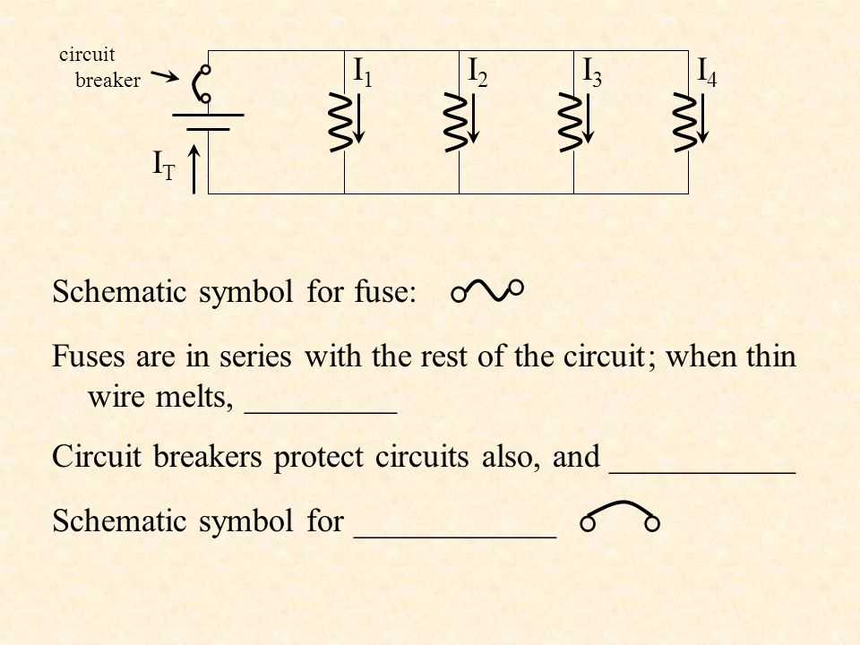
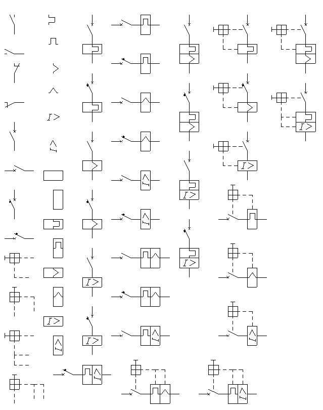
Circuit breaker schematics often include symbols and labels that represent different components such as switches, fuses, relays, and protective devices. These symbols help simplify the diagram and make it easier to understand the circuit’s functionality.
Understanding the basics of circuit breaker operation and the components involved is essential for proper installation, maintenance, and troubleshooting. It ensures the safe and efficient operation of electrical systems and helps prevent accidents and damage to equipment.
Components of a Circuit Breaker

A circuit breaker is an essential component of an electrical system. It is designed to protect the system from overloads and short circuits by interrupting the flow of current when necessary. Understanding the different components of a circuit breaker can help in understanding its operation and the role it plays in maintaining the safety of an electrical system.
1. Contacts: The contacts in a circuit breaker are responsible for carrying the current and interrupting it when necessary. They are usually made of a durable material, such as copper, and are designed to withstand high temperatures and electrical arcs.
2. Operating Mechanism: The operating mechanism of a circuit breaker is responsible for controlling the opening and closing of the contacts. It can be manual, where a person physically operates the breaker, or automatic, where an electromechanical or electronic device triggers the opening or closing of the contacts.
3. Trip Unit: The trip unit is a crucial component of a circuit breaker that detects abnormal current conditions, such as an overload or a short circuit, and triggers the opening of the contacts. It can be thermal, based on the heat generated by the current, or magnetic, based on the magnetic field created by the current.
4. Arc extinguisher: When the contacts of a circuit breaker open, an arc is created due to the sudden interruption of current flow. The arc extinguisher is responsible for quickly extinguishing this arc to prevent damage to the surrounding equipment and ensure safe operation.
5. Frame: The frame of a circuit breaker provides the structural support and housing for all the internal components. It is designed to be durable and able to withstand environmental conditions, such as temperature and humidity.
In conclusion, a circuit breaker consists of various components that work together to protect an electrical system from overloads and short circuits. The contacts, operating mechanism, trip unit, arc extinguisher, and frame each play a vital role in ensuring the safe and efficient operation of the circuit breaker.
Types of Circuit Breaker Schematics
A circuit breaker is an essential component in any electrical system as it helps protect the circuit from overloads, short circuits, and faults. There are different types of circuit breaker schematics available, each designed to suit specific applications and voltage levels.
1. Air Circuit Breaker (ACB)
An air circuit breaker is a type of circuit breaker that uses air as the medium to extinguish the arc that forms when the circuit is interrupted. It consists of a set of contacts enclosed in a sealed container filled with pressurized air. When the circuit breaker is tripped, the contacts open, and the arc is drawn into the container, where it is quenched by the air. Air circuit breakers are commonly used in low-voltage applications.
2. Vacuum Circuit Breaker (VCB)
A vacuum circuit breaker is a type of circuit breaker that uses a vacuum as the arc-quenching medium. It consists of a set of contacts enclosed in a vacuum-sealed container. When the circuit breaker is tripped, the contacts open, and the arc is extinguished by the vacuum. Vacuum circuit breakers are typically used in medium-voltage applications.
3. Molded Case Circuit Breaker (MCCB)
A molded case circuit breaker is a type of circuit breaker that is enclosed in a molded case made of insulating material. It consists of a set of contacts, an operating mechanism, and protection against overloads and short circuits. Molded case circuit breakers are commonly used in residential, commercial, and industrial applications.
4. Miniature Circuit Breaker (MCB)
A miniature circuit breaker is a type of circuit breaker that is designed for low-voltage applications. It is compact in size and can be easily installed in electrical distribution boards. Miniature circuit breakers provide protection against overloads and short circuits and are commonly used in residential and commercial buildings.
5. Residual Current Circuit Breaker (RCCB)
A residual current circuit breaker, also known as an earth leakage circuit breaker, is a type of circuit breaker that provides protection against electric shock and fire hazards caused by ground fault currents. It detects any imbalance between the incoming and outgoing currents and trips the circuit breaker to prevent electrical accidents. Residual current circuit breakers are commonly used in buildings with sensitive electrical equipment and in outdoor installations.
In conclusion, there are various types of circuit breaker schematics available, each designed to meet specific requirements and applications. Choosing the right circuit breaker schematic is crucial for ensuring the safety and reliability of the electrical system.
How Circuit Breakers Work

A circuit breaker is an electrical device designed to protect an electrical circuit from damage caused by excess current flow. It acts as a switch that automatically opens when the current exceeds a certain level, preventing damage to the circuit and any devices connected to it. Circuit breakers are commonly used in residential, commercial, and industrial buildings, as well as in power distribution systems.
The basic principle of how a circuit breaker works is relatively simple. When the current flowing through the circuit exceeds the rated capacity of the breaker, an electromagnet is activated. This electromagnet pulls a lever, causing the circuit breaker contacts to open and interrupt the flow of current. In some circuit breakers, a bimetallic strip is used instead of an electromagnet. The bimetallic strip bends when it gets heated due to excess current, tripping the breaker and opening the circuit.
There are different types of circuit breakers, including thermal-magnetic circuit breakers and residual current circuit breakers (RCCBs). Thermal-magnetic circuit breakers use both a bimetallic strip and an electromagnet to trip the breaker. The bimetallic strip provides protection against overcurrents that last for longer durations, while the electromagnet provides protection against short-circuit currents. RCCBs, on the other hand, are designed to detect small leakage currents caused by faults in the electrical system. When a fault is detected, the RCCB trips and disconnects the circuit from the power source.
Circuit breakers play a crucial role in electrical safety. They protect circuits from overloading and short circuits, which can lead to fires and other hazards. In addition, circuit breakers allow for easier troubleshooting and maintenance, as they can be easily reset after they trip. Overall, circuit breakers are an essential component of any electrical system, ensuring the safety and reliability of the electrical circuits they protect.
Benefits and Applications of Circuit Breaker Schematics
Circuit breaker schematics are an essential tool for understanding and troubleshooting electrical systems. They provide a visual representation of the circuitry and the flow of electricity, allowing engineers and technicians to identify potential issues and make informed decisions about maintenance and repairs. The following are some of the key benefits and applications of circuit breaker schematics:
1. Fault Detection and Isolation
One of the primary uses of circuit breaker schematics is to detect and isolate faults in electrical systems. By studying the schematic diagram, technicians can easily identify the components and connections involved in a particular circuit. This facilitates the process of locating faulty components or connections and helps in the timely resolution of issues, preventing further damage and downtime.
2. Troubleshooting and Repair
When an electrical system malfunctions, technicians can refer to the circuit breaker schematic to understand how the circuit is supposed to operate. This allows them to systematically troubleshoot and identify the root cause of the problem. By following the flow of electricity indicated in the schematic, technicians can pinpoint the specific component or connection that needs to be repaired or replaced, minimizing downtime and reducing the time required for troubleshooting.
3. System Upgrades and Modifications
Circuit breaker schematics play a crucial role in system upgrades and modifications. When introducing new components or altering existing connections, engineers can refer to the schematics to ensure that the changes are integrated correctly and won’t cause any adverse effects on the overall system. Having an accurate representation of the existing circuitry helps in planning and implementing upgrades or modifications efficiently and effectively.
4. Training and Education
Circuit breaker schematics are widely used in training and educational programs for aspiring electrical engineers and technicians. By studying and analyzing schematics, students can gain a deeper understanding of electrical circuits, circuitry design, and the principles of electricity. Schematics provide a visual representation that helps students grasp complex concepts and theories, making it easier for them to apply their knowledge in real-world scenarios.
5. Compliance and Safety
Circuit breaker schematics are essential for ensuring compliance with safety standards and regulations. They help in designing and implementing electrical systems that meet the necessary safety requirements, such as proper grounding, insulation, and protection against overloads and short circuits. Schematics also aid in documenting and communicating the safety features and specifications of electrical systems, facilitating maintenance and inspections.
In conclusion, circuit breaker schematics offer numerous benefits and applications in the field of electrical engineering. They assist in fault detection, troubleshooting, system upgrades, training, and ensuring safety compliance. By leveraging the visual representation provided by schematics, engineers and technicians can effectively understand, maintain, and optimize electrical systems.
Common Issues and Troubleshooting Tips
Understanding common issues and knowing how to troubleshoot them can help you resolve problems with your circuit breaker schematic more effectively. Here are some common issues and troubleshooting tips:
1. Circuit Breaker Tripping Frequently
If your circuit breaker frequently trips, it could indicate an overloaded circuit. Check the load capacity of the circuit and make sure you are not exceeding it. You may need to redistribute the load, add a dedicated circuit, or upgrade the circuit breaker to a higher amperage rating.
2. Circuit Breaker Not Tripping
If the circuit breaker does not trip when it should, there may be a fault in the circuit. Inspect the wiring and connections for any signs of damage or loose connections. Use a multimeter to check for continuity and proper voltage. If necessary, replace faulty components or consult a professional electrician.
3. Circuit Breaker Won’t Reset
If the circuit breaker won’t reset, it could be due to a persistent fault or a malfunctioning breaker. Disconnect all devices from the circuit and attempt to reset the breaker. If it still won’t reset, there may be an underlying issue with the breaker itself. Consider replacing the breaker or seeking professional assistance.
4. Inconsistent Power Supply
If you are experiencing inconsistent power supply, it could be caused by a loose connection or a faulty breaker. Check the connections and tighten any loose wires. Inspect the breaker for signs of damage or malfunction. If necessary, replace the breaker or consult an electrician for further assistance.
5. Electrical Overheating
If you notice any signs of electrical overheating, such as burning smells or discolored outlets, it is important to address the issue promptly. Overheating can be caused by an overloaded circuit, loose connections, or a faulty breaker. Reduce the load on the circuit, tighten any loose connections, and inspect the breaker for any signs of damage. If the issue persists, consult a professional electrician.
Remember, always prioritize safety when working with electrical systems. If you are unsure or uncomfortable with troubleshooting electrical issues, it is always best to consult a professional electrician.