
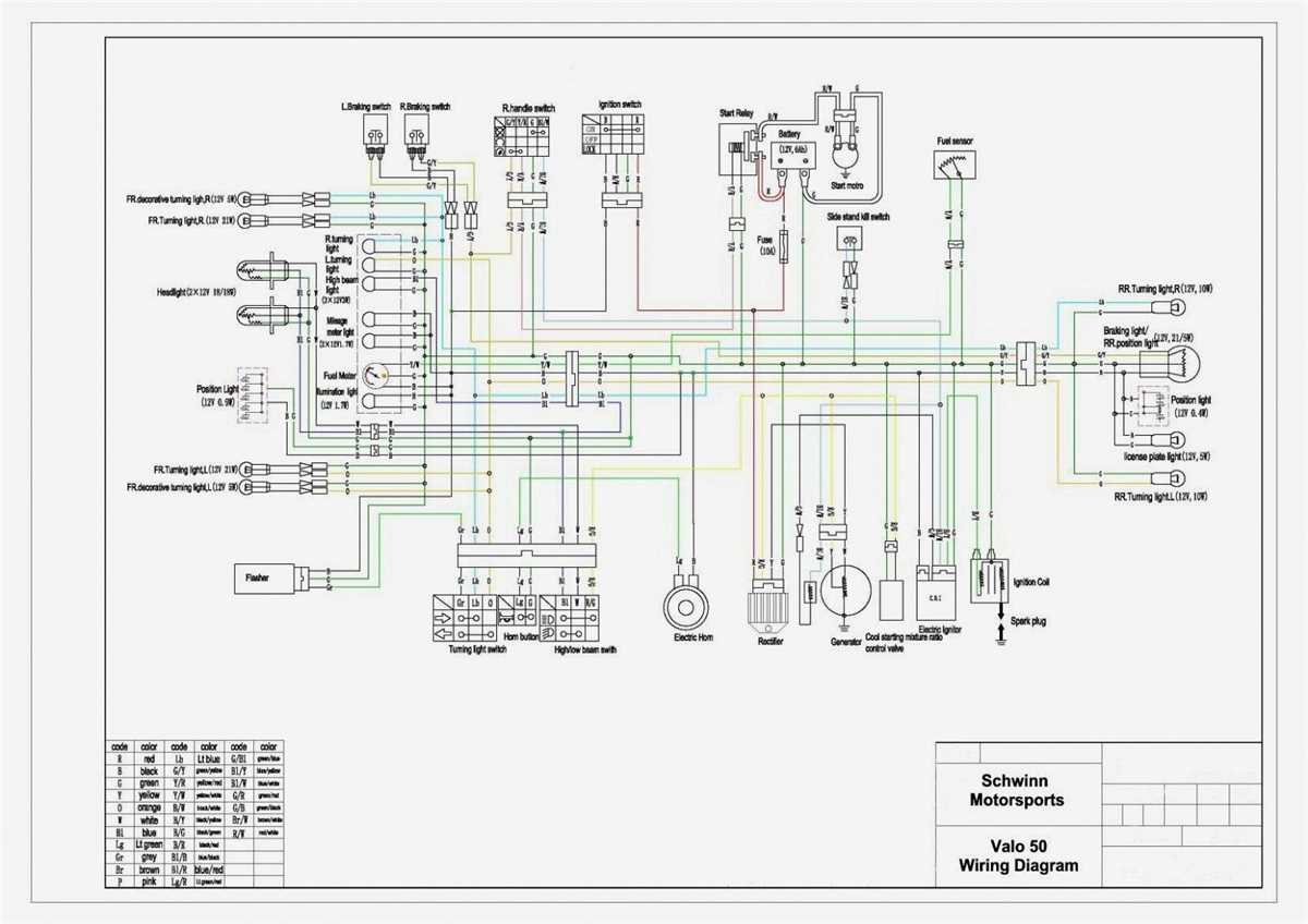
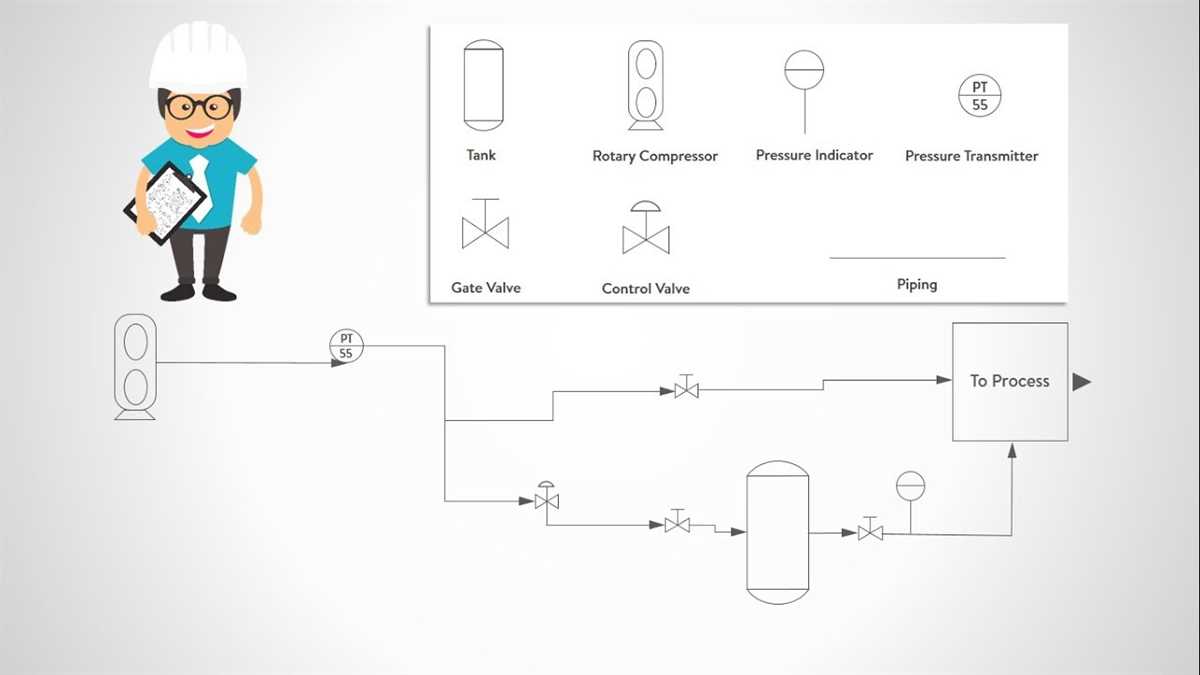
A circuit diagram is a graphical representation of an electrical circuit. It uses standardized symbols to show the components and connections in the circuit. To understand a circuit diagram, it is important to know the meaning of these symbols. This is where the circuit diagram legend comes into play.
The circuit diagram legend is a key that explains the symbols and their meanings. It provides a reference guide for engineers, technicians, and hobbyists to understand and interpret circuit diagrams. Each symbol in the legend represents a specific component or function in a circuit, such as resistors, capacitors, transistors, and power sources.
In addition to the symbols, the legend may also include labels or abbreviations to further clarify the purpose of each component. For example, a resistor symbol in the legend may be labeled with its resistance value in ohms. This helps the reader quickly identify and grasp the essential details of the circuit diagram.
Overall, the circuit diagram legend is an essential tool for anyone involved in electronics. It provides a standardized and universal language for representing circuit components and connections. By familiarizing oneself with the legend, one can effectively read, interpret, and analyze circuit diagrams, enabling the design, troubleshooting, and repair of electrical circuits.
Circuit Diagram Legend
A circuit diagram legend is a key or guide to understanding the symbols and notations used in circuit diagrams. Circuit diagrams are schematic representations of electrical circuits, and they are used by engineers, electricians, and technicians to design, analyze, and troubleshoot electrical systems. Understanding the symbols and notations in a circuit diagram is essential for interpreting the information and correctly implementing the circuit.
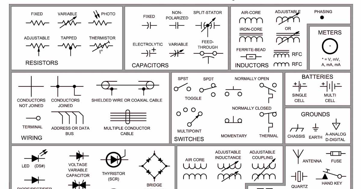
The circuit diagram legend typically includes a range of symbols and their corresponding meanings. Some common symbols found in circuit diagrams include resistors, capacitors, inductors, diodes, transistors, switches, and various types of connectors. Additionally, the legend may also provide information about the directions of current flow, voltage polarity, and other important parameters.
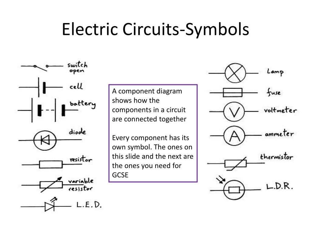
Resistors: Resistors are represented by a zigzag line or a rectangular box. They are used to control the flow of current in a circuit and are measured in ohms (Ω).
Capacitors: Capacitors are represented by parallel lines or curved plates. They store and release electrical energy and are measured in farads (F).
Inductors: Inductors are represented by coils or spirals. They store and release magnetic energy and are measured in henries (H).
Diodes: Diodes are represented by a triangle with a line attached. They allow current to flow in one direction and block it in the opposite direction.
Transistors: Transistors are represented by various symbols depending on their type (bipolar junction transistor, field-effect transistor, etc.). They are used to amplify or switch electronic signals.
Switches: Switches are represented by different types of lines and contacts. They control the flow of current in a circuit and can be either open (off) or closed (on).
Connectors: Connectors are represented by dots, lines, or specific shapes. They represent points where different components or wires are connected.
By referring to the circuit diagram legend, engineers and technicians can easily identify and interpret the various symbols and notations used in a circuit diagram. This allows them to analyze and troubleshoot electrical systems efficiently, ensuring that circuits are properly designed and functioning correctly.
What is a Circuit Diagram Legend?
A circuit diagram legend, also known as a circuit diagram key or symbol legend, is a guide that provides a clear representation of the symbols used in a circuit diagram. It helps to understand the various components and connections in an electrical circuit. The legend is typically placed near the diagram and contains a list of symbols along with their corresponding meanings.
The circuit diagram legend plays a vital role in electrical engineering and electronics. It ensures that anyone viewing the diagram can easily interpret the symbols and understand the circuit’s design and functionality. Without a legend, a circuit diagram can be confusing, especially for individuals who are not familiar with the standard symbols used in electrical engineering.
In a circuit diagram legend, the symbols are typically categorized and organized in a logical manner. Common components such as resistors, capacitors, diodes, transistors, and switches are represented by specific symbols. Each symbol is accompanied by a label or description that explains its purpose or function in the circuit.
Additionally, a circuit diagram legend may also include other important information such as voltage and current ratings, polarity indications, and notes about specific connections or configurations. This helps to provide a comprehensive understanding of the circuit and allows engineers, technicians, or hobbyists to troubleshoot or modify it if needed.
Overall, a circuit diagram legend serves as a visual aid that simplifies the interpretation and analysis of complex electrical circuits. It allows engineers and technicians to communicate their designs effectively and enables others to replicate or understand the circuit’s operation without any confusion.
The Importance of a Circuit Diagram Legend
A circuit diagram legend, also known as a symbol legend or key, is a crucial component of any circuit diagram. It provides a visual reference for the different symbols and their meanings used in the diagram. This allows anyone reading the diagram to easily understand and interpret the circuit’s design and functionality. Without a clear and concise legend, a circuit diagram can become confusing and difficult to interpret, leading to errors in understanding and implementation.
Organization and Clarity: One of the main reasons why a circuit diagram legend is important is that it helps to organize and provide clarity to the circuit diagram. By assigning specific symbols to different components or functions, the legend ensures that the diagram remains visually clean and uncluttered. This helps to prevent confusion and makes it easier for individuals to follow and understand the circuit’s design.
Consistency and Standardization: A circuit diagram legend also serves as a means of maintaining consistency and standardization within the field of electronics. By adhering to universally accepted symbols and their meanings, the legend ensures that different individuals or organizations can easily communicate and understand circuit designs. This is particularly important when it comes to collaboration, troubleshooting, and design modifications, as a standardized symbol legend allows for easy interpretation and discussion.
Efficiency and Time-Saving: Another key advantage of a circuit diagram legend is that it promotes efficiency and saves time. Rather than having to explain the meaning of each symbol used in the diagram individually, the legend provides a quick reference guide. This enables individuals to quickly identify and understand the different components or functions represented by the symbols, allowing them to proceed with the design or troubleshooting process more efficiently.
Training and Education: Circuit diagram legends are essential in training and education settings, where individuals are learning about electronics and circuit design. By using a legend, instructors can teach students about the different symbols and their meanings, enabling them to read and interpret circuit diagrams effectively. This fosters a better understanding of electronics principles and enhances students’ ability to design and troubleshoot circuits in real-world applications.
In conclusion, a circuit diagram legend is a vital tool in the field of electronics. It provides organization, clarity, consistency, efficiency, and educational support. By ensuring that symbols are accurately represented and easily understood, a circuit diagram legend helps prevent errors, promotes effective communication, and facilitates the design and troubleshooting of circuits.
Components in a Circuit Diagram Legend
In a circuit diagram, various components are represented by specific symbols. These symbols are used to provide a clear and concise representation of the different elements present in a circuit. A circuit diagram legend is a key that explains these symbols and helps users understand the meaning of each symbol in the diagram.
Here are some common components that are typically included in a circuit diagram legend:
- Resistor: Represented by a zigzag line, a resistor is a passive two-terminal electrical component that limits or regulates the flow of electric current in a circuit.
- Capacitor: Shown as two parallel lines, a capacitor is a device that stores electrical energy in an electric field. It is often used to store and release energy in circuits.
- Inductor: Represented by a coil or a series of loops, an inductor is a passive electrical component that stores energy in a magnetic field. It is commonly used in circuits to control the flow of current.
- Diode: Displayed as a triangle with a line, a diode is a semiconductor device that allows current to flow in one direction while blocking it in the opposite direction. It is often used as a rectifier in circuits.
- Transistor: Shown as three interconnected lines, a transistor is a semiconductor device that can amplify or switch electronic signals and electrical power. It is widely used in various electronic devices.
- Switch: Represented by a line with a break or a dot, a switch is an electrical component that can open or close a circuit, allowing or inhibiting the flow of electricity.
These are just a few examples of components that may be included in a circuit diagram legend. The legend ensures that anyone reading the diagram can easily interpret and understand the various symbols used, enabling them to analyze and troubleshoot the circuit effectively.
Common Symbols in a Circuit Diagram Legend
The symbols used in a circuit diagram legend represent various components and devices found in electrical circuits. These symbols are standardized and universally recognized by electrical engineers and technicians.
1. Resistor: The symbol for a resistor is a zigzag line. It represents a device used to limit the flow of electric current in a circuit.
2. Capacitor: The symbol for a capacitor is two parallel lines, usually with a curved line between them. It represents a device used to store and release electrical energy.
3. Inductor: The symbol for an inductor is a coiled wire. It represents a device used to store and release magnetic energy in a circuit.
4. Diode: The symbol for a diode is an arrow pointing towards a line. It represents an electronic device that allows current to flow in one direction only.
5. Transistor: The symbols for different types of transistors vary, but they generally consist of three layers or regions connected by arrows. Transistors are used to amplify or switch electronic signals.
6. Switch: The symbol for a switch is a line with a gap in the middle. It represents a device used to open or close an electrical circuit.
7. Battery: The symbol for a battery is two parallel lines, one longer than the other, with plus and minus signs. It represents a device that generates and stores electrical energy.
8. Ground: The symbol for ground is a horizontal line with three downward-pointing lines. It represents a reference point in an electrical circuit.
9. Ammeter: The symbol for an ammeter is a circle with a letter “A” inside. It represents a device used to measure the flow of electric current in a circuit.
10. Voltmeter: The symbol for a voltmeter is a circle with a letter “V” inside. It represents a device used to measure the voltage or potential difference between two points in a circuit.
- Resistor: Zigzag line
- Capacitor: Two parallel lines with a curved line between them
- Inductor: Coiled wire
- Diode: Arrow pointing towards a line
- Transistor: Various symbols representing three layers or regions connected by arrows
- Switch: Line with a gap in the middle
- Battery: Two parallel lines, one longer than the other, with plus and minus signs
- Ground: Horizontal line with three downward-pointing lines
- Ammeter: Circle with the letter “A” inside
- Voltmeter: Circle with the letter “V” inside
These are just a few examples of the common symbols found in a circuit diagram legend. Learning and understanding these symbols is essential for anyone working with electrical circuits, as they allow for clear and easy communication of circuit designs and components.
Additional Symbols in a Circuit Diagram Legend
In addition to the basic symbols used in a circuit diagram legend, there are also several additional symbols that may be included to represent specific components or functions within a circuit. These additional symbols provide more detailed information and allow for a clearer representation of the circuit’s design.
One common additional symbol is the resistor with a diagonal line through it, which represents a variable resistor. This symbol is used to indicate that the resistance value of the component can be adjusted manually, allowing for control over the flow of current in the circuit.
Another additional symbol is the coil or inductor, which is represented by a series of curved lines. Inductors are used to store and release energy in a circuit, and the symbol helps to identify their presence within the circuit diagram.
The transformer is another component that is often represented by an additional symbol. The symbol consists of two coils, often with different numbers of turns, and represents the ability of a transformer to convert voltage levels within a circuit.
Other additional symbols that may be included in a circuit diagram legend include capacitors (represented by two parallel lines), diodes (represented by an arrow pointing in one direction), and transistors (represented by a combination of circles and lines). Each of these symbols provides important information about the specific components used in the circuit and their function within the overall design.
Tips for Understanding a Circuit Diagram Legend

A circuit diagram legend is a key component in understanding a circuit diagram. It provides all the necessary information about the symbols and labels used in the diagram. To effectively understand a circuit diagram legend, here are some tips to keep in mind:
- Familiarize Yourself with the Symbols: Take the time to learn and understand the various symbols used in circuit diagrams. Refer to the legend for definitions and explanations. This will help you interpret the diagram accurately.
- Note the Labels: Labels are essential in circuit diagrams, as they provide information about the components used. Be sure to read and understand the labels associated with each symbol to correctly identify and locate components in the circuit.
- Pay Attention to the Arrows: Arrows in a circuit diagram indicate the direction of the current flow. Make sure to follow the direction indicated by the arrows to understand the sequence of the circuit.
- Refer to the Legend Frequently: When working with a circuit diagram, keep the legend within reach. Constantly referring to the legend will help you avoid confusion and ensure accurate interpretation of the diagram.
- Take Advantage of Additional Information: Some circuit diagram legends may include additional information, such as color codes or specific measurements. These details can provide further clarity and understanding of the circuit.
By following these tips and utilizing the information provided in the circuit diagram legend, you will be better equipped to understand and interpret circuit diagrams effectively.
Q&A:
What is a circuit diagram legend?
A circuit diagram legend is a key or legend that provides a visual representation of the symbols and abbreviations used in a circuit diagram.
Why is it important to understand a circuit diagram legend?
Understanding a circuit diagram legend is important because it allows you to correctly interpret and understand the various symbols and abbreviations used in a circuit diagram. This understanding is essential for troubleshooting, repairing, or building electronic circuits.
What are some common symbols found in a circuit diagram legend?
Some common symbols found in a circuit diagram legend include resistor symbols, capacitor symbols, diode symbols, transistor symbols, and various types of switch symbols.
How can I learn to understand a circuit diagram legend?
You can learn to understand a circuit diagram legend by studying the various symbols and abbreviations used in electronic circuits, referring to textbooks or online resources that explain the meaning of these symbols, and practicing interpreting circuit diagrams.
Are circuit diagram legends standardized?
There is no universal standard for circuit diagram legends, but there are commonly used symbols and abbreviations that are widely recognized and understood in the field of electronics.