If you’re troubleshooting or replacing parts of a hydraulic system that engages the transmission, it’s crucial to identify the key components that enable smooth shifting. One such component is the device responsible for converting pedal pressure into hydraulic force, which allows the system to disengage the gears efficiently.
Focus on the component that houses a reservoir and utilizes a piston to pressurize the fluid, triggering the mechanism that separates the clutch and flywheel. This system is vital for providing the necessary force to operate the pressure plate, and any malfunction can directly impact your vehicle’s shifting performance.
To understand how these parts interact, refer to a detailed schematic of the hydraulic system. Look for a cross-sectional view showing how the fluid travels through connected pipes and how the piston moves in response to the pedal’s force. The correct interpretation of this structure will guide your troubleshooting or installation process, ensuring proper functionality.
Make sure to check the orientation and alignment of the main sealing elements, as leaks or wear here can lead to a loss of hydraulic pressure. Knowing the specifics of these components, their placement, and their interaction with other parts will help you maintain or repair the system effectively.
Understanding Hydraulic System Components for Gear Shifting
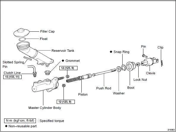
For a smooth gear engagement, ensure the hydraulic piston assembly is in proper working condition. If you’re facing issues like delayed or unresponsive shifting, it’s often linked to air or fluid leaks within this crucial part of the transmission setup. Inspect the fluid reservoir and plunger regularly for optimal performance. A malfunction in the sealing components of the actuation chamber can lead to ineffective operation, causing excessive pedal play or difficulty in disengaging the gears.
The primary piston and its pushrod must move freely, with no obstructions or rust buildup. When servicing this unit, confirm that the reservoir ports are clean and that no contamination or wear is present around the seal housing. Regularly check the fluid for debris or discoloration, which may indicate internal damage.
In case of hydraulic fluid leakage, inspect the seal ring and replace it if worn. Also, verify that the fluid line connections are tightly secured. If the pressure within the system seems inconsistent, recalibrate the actuating force to avoid further transmission malfunctions.
How to Interpret a Hydraulic System Schematic for Troubleshooting

Begin by identifying the main components involved: the pump, reservoir, and release mechanism. Focus on the flow paths between these parts. The flow direction is usually marked with arrows, helping you trace fluid movement under pressure.
- Check for Blockages: Look for areas where flow might be restricted. A sudden change in pipe size or bends could indicate a potential clog or air bubble.
- Inspect Fluid Paths: Follow the lines to ensure the fluid travels as expected. If the diagram shows a branching path, confirm each branch is connected correctly and securely.
- Pressure Zones: Some systems include pressure-sensitive zones. These areas are critical for ensuring proper force transmission. Check for any inconsistencies in these regions, as they could signal pressure loss.
Next, focus on the connections and joints. Leaking seals or loose fittings are common failure points. Verify each connection for signs of wear or fluid seepage, as this could lead to inefficiencies.
- Examine Seals: Leaky seals can cause fluid loss and inconsistent operation. If the diagram highlights seal locations, ensure these are intact and properly seated.
- Verify Fluid Levels: Low fluid levels can impact system performance. Ensure the reservoir is filled according to the schematic, and confirm no leaks are draining the fluid.
- Check for Consistent Pressure: Any fluctuation or drop in pressure at critical points could indicate a malfunction. Look for pressure release valves and ensure they are in the correct position.
Finally, cross-reference the schematic with real-world observations. Compare any anomalies with the labeled components on the diagram to pinpoint potential issues quickly. This methodical approach helps isolate faults, enabling efficient repair or adjustment.
Key Components and Their Functions in a Hydraulic Actuation System

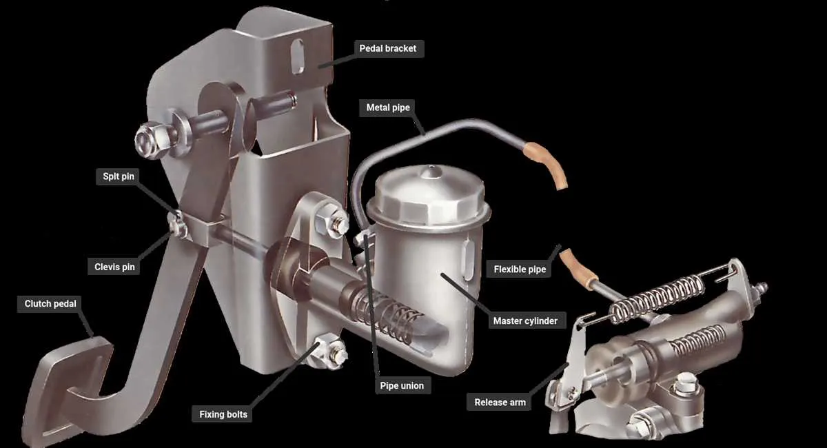
The primary components of a hydraulic actuation system are essential for effective transmission control. Each part plays a vital role in transmitting force from the pedal to the release mechanism. Understanding their functions is crucial for efficient system performance and troubleshooting.
Reservoir – Located at the top of the system, the fluid reservoir stores hydraulic fluid necessary for operation. It ensures there is enough fluid to maintain pressure and enable smooth engagement and disengagement of the gear mechanism. Keep it filled to avoid air entering the system, which can cause performance issues.
Piston and Bore – The piston inside the bore is responsible for generating hydraulic pressure. When the pedal is depressed, the piston moves, pushing fluid into the lines, which activates the slave mechanism. The bore ensures the piston moves smoothly and seals properly to prevent leakage.
Seal Kit – Seals prevent fluid leakage at various points where components meet. A properly functioning seal kit ensures pressure is maintained within the system, improving efficiency and reducing wear on the moving parts. Regular inspection of seals for wear is essential to avoid fluid loss.
Push Rod – The push rod connects the pedal assembly to the piston. It transmits the mechanical force exerted by the foot on the pedal into hydraulic force. If the push rod is misaligned or damaged, the entire system can fail to activate the release mechanism.
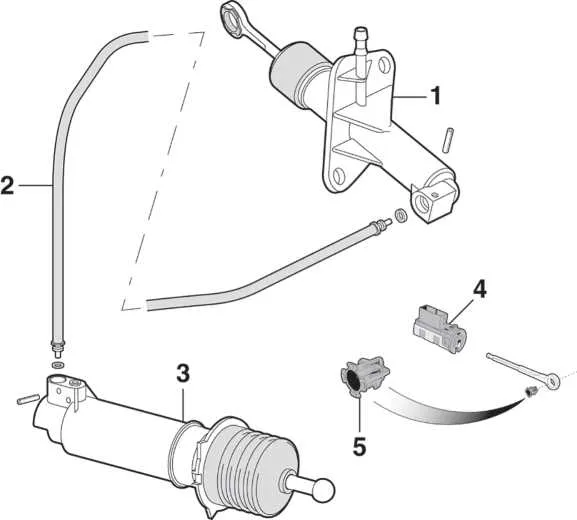
Hydraulic Lines – These lines carry pressurized fluid between the components. They must be intact, free from kinks, and properly secured. Any blockage or leakage in the lines can lead to a loss of pressure, making the system ineffective.
Pressure Plate Mechanism – This component receives the hydraulic pressure and uses it to disengage the clutch. It must respond promptly and consistently to fluid pressure to ensure smooth gear shifts. Any delay or inconsistency in response can lead to difficulty in shifting or slipping.
Common Issues with Hydraulic Pedal Components and How to Fix Them
Leaks in the hydraulic system are often the cause of insufficient pedal pressure. Inspect the seals and hoses for any visible cracks or wear. If a leak is found, replace the faulty part immediately to restore function.
If the pedal feels soft or spongy, air might have entered the hydraulic lines. Bleed the system thoroughly to remove trapped air and ensure a firm pedal response. Using a vacuum pump can expedite this process and minimize the risk of introducing additional air.
Inconsistent pedal engagement is typically a sign of internal wear or contamination. Check the fluid level and quality–low or dirty fluid can cause poor performance. Flush the system and refill with fresh, manufacturer-recommended fluid to prevent further damage.
When the pedal does not return properly, a worn return spring or a blockage in the fluid lines could be the issue. Examine the spring for damage and ensure no debris is obstructing the flow of fluid. Replace any damaged parts to restore normal operation.
Difficulty in disengaging the transmission may be caused by faulty seals or misalignment of the pushrod. Inspect and adjust the pushrod for proper alignment and replace any worn seals to improve engagement.
Rough or erratic pedal feel can indicate a problem with the fluid reservoir. Ensure the reservoir cap is tight and the fluid is at the correct level. If the fluid appears discolored or contaminated, perform a complete flush to avoid further issues.