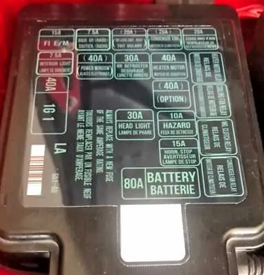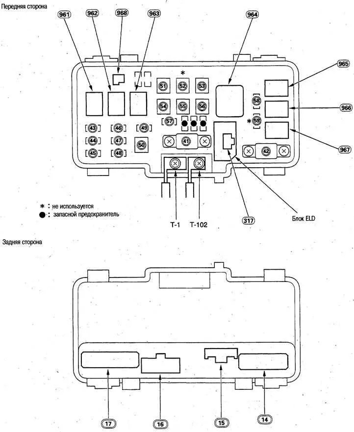
Locate the driver-side panel beneath the dashboard near the left kick panel. Remove the plastic cover to reveal the charted allocations. The upper left corner generally holds controls tied to illumination, including tail and corner lighting. Adjacent slots often manage power windows and accessory outlets.
Inspect the engine bay distribution unit next to the battery. This section governs high-amperage circuits such as the cooling fan motor, ignition coil, and primary relay feeds. A 100A main feed typically sits at the topmost location, marked with a metal terminal screw.
Replace any blown elements with components rated identically by amperage. For instance, a 15A slot serving the fuel injection module must not be substituted with a 20A part. Mismatches can trigger thermal overload and component failure.
Consult the rear trunk-side compartment only if optional features are installed. This space occasionally hosts regulators tied to the audio amplifier or optional anti-theft modules. Not all trims include this third section.
Relay Layout and Circuit Protection Map
Locate the interior relay hub beneath the dashboard on the driver’s side, just above the kick panel. The 7.5A slot marked “ACC” handles accessory electronics such as the stereo and cigarette lighter. Adjacent, the 10A labeled “SRS” is dedicated to the supplemental restraint system.
Under the hood, the primary module sits adjacent to the battery. The 30A marked “Cooling Fan” ensures proper radiator airflow. The 40A marked “Heater Motor” powers the cabin climate system. A separate 15A marked “Fuel Pump” supports the delivery system from the tank.
Always match the amperage rating during replacement to avoid electrical faults. If lights fail, check the 15A labeled “Tail Light” under the dashboard, and for power windows, refer to the 20A slot designated for “Window”.
Consult the panel lid markings or owner’s guide to confirm slot assignments, especially when dealing with features like the ABS controller (20A) or rear defogger (30A).
Identifying Fuse Locations Under the Hood and Dashboard

Begin by opening the hood and locating the rectangular black compartment near the battery on the driver’s side. Release the latch and examine the underside of the lid to view the labeled layout. Key circuits such as the radiator fan, ignition switch, and fuel pump connections are typically housed here. Use needle-nose pliers to extract components safely.
Inside the cabin, look beneath the steering wheel near the left kick panel. Remove the plastic cover by pulling it gently from the top edge. Essential elements related to lighting, wipers, and audio are arranged in this lower section. Match each slot to the legend etched on the interior cover or printed beside the holder. Always disconnect the negative battery terminal before inspection or replacement.
Understanding Assignments for Key Electrical Systems
Prioritize inspecting the power distribution layout related to ignition, lighting, and charging modules. The relay panel typically includes dedicated slots with numeric labeling that correspond to individual circuits. Refer to the internal lid chart to match these positions with specific systems.
- Position 1: Usually linked to the starter solenoid and ignition control; verify continuity if engine crank fails.
- Slot 7: Frequently routes current to low-beam headlights; replace element if dimming or outage occurs on both sides.
- Location 15: Allocated to instrument cluster and speed sensor; a non-responsive dash may signal a blown unit here.
- Channel 20: Supports power window regulators and central locking; essential when doors or windows are non-functional.
- Entry 22: Powers ECU and fuel delivery module; misfires or starting delays can originate from a faulty component here.
Always match amperage ratings during replacement. A higher-rated substitute can cause overheating in sensitive conductors, while an underrated one may trigger false interruptions. For troubleshooting, a test light or multimeter should be used at the terminal end to confirm live voltage and ground presence before replacing any part.
Troubleshooting Common Electrical Failures Using the Wiring Layout
Start by locating the specific circuit responsible for the malfunctioning component using the detailed schematic. Check the integrity of the protective elements assigned to that circuit by visually inspecting their condition and testing continuity with a multimeter.
If a component such as headlights or radio loses power, identify the corresponding link in the schematic and test the conductor path for breaks or corrosion. Pay attention to connectors and terminals as they often cause intermittent issues due to oxidation or looseness.
When dealing with repeated power interruptions in accessories, trace the wiring harness segments indicated on the electrical plan, focusing on areas prone to wear, like under the dashboard or near the engine bay. Replace any damaged wiring or connectors found during inspection.
Use the reference chart to verify amperage ratings for each protective element. Substituting with a higher rating can lead to component damage, while a lower rating may cause frequent cutoffs. Always match the exact rating specified in the circuit overview.
For systems controlled by relays, consult the schematic to test coil activation and contact resistance. A faulty relay often mimics fuse-related symptoms but requires a different diagnostic approach involving voltage checks at terminals.
Consult the detailed map to locate grounding points essential for proper circuit function. Poor ground connections often result in erratic behavior or total loss of power in specific electrical modules. Clean and tighten all grounding screws and bolts.