The Compustar CM900AS is a popular car alarm and remote start system that provides convenience and security to vehicle owners. Installing this system requires a good understanding of the wiring connections to ensure a seamless integration with the vehicle’s electrical system.
In this article, we will explore the wiring diagram of the Compustar CM900AS and discuss the various connections involved. This comprehensive diagram provides a visual representation of how the system connects to different components of the vehicle, such as the ignition, starter, power locks, and more.
One of the key aspects of the Compustar CM900AS wiring diagram is understanding the color codes used for the different wires. The diagram usually includes a legend that explains what each color represents, making it easier to identify the corresponding wires during installation or troubleshooting.
It’s important to note that the wiring connections may vary depending on the make and model of the vehicle. Therefore, it’s essential to refer to the specific wiring diagram provided by Compustar for the CM900AS system and consult the vehicle’s technical manual for accurate information.
Compustar CM900AS wiring diagram: A comprehensive guide
The Compustar CM900AS is a popular car alarm and remote start system that provides enhanced security and convenience for your vehicle. If you are planning to install this system in your car, it is essential to have a comprehensive understanding of the wiring diagram to ensure a successful installation.
The wiring diagram for the Compustar CM900AS consists of various components and connections that need to be properly set up. It includes the main control module, door sensors, ignition switch, valet switch, hood pin switch, parking light output, and many more. Each component has specific wiring connections that must be followed to ensure proper functionality.
Here is a breakdown of the key components and their wiring connections:
- Main Control Module: The main control module serves as the brain of the system. It requires power and ground connections, as well as connections to the ignition switch, door sensors, and other peripherals.
- Door Sensors: The door sensors are responsible for detecting when the doors are opened or closed. They need to be wired to the corresponding door triggers in the vehicle.
- Ignition Switch: The ignition switch connection enables the system to detect the status of the ignition. This connection is crucial for the remote start functionality of the CM900AS.
- Valet Switch: The valet switch allows you to enable or disable certain features of the system. It should be wired to a convenient location inside the vehicle.
- Hood Pin Switch: The hood pin switch ensures that the engine will not start when the hood is open. It needs to be wired to the hood latch mechanism.
- Parking Light Output: The parking light output connection allows the CM900AS to flash the vehicle’s parking lights as a visual confirmation of certain system actions.
It is important to follow the specific wiring instructions provided in the Compustar CM900AS user manual or installation guide. Each vehicle may have slightly different wiring requirements, so it is crucial to consult the appropriate documentation for your specific make and model.
Overall, understanding the wiring diagram of the Compustar CM900AS is essential for a successful installation. By following the proper wiring connections, you can ensure that the system functions correctly and provides the security and convenience features you desire for your vehicle.
Overview of the CM900AS security system
The CM900AS is a comprehensive and advanced security system designed to protect vehicles from theft and unauthorized access. It offers a wide range of features and capabilities to ensure the safety and security of the vehicle and its occupants.
The CM900AS security system includes a variety of components, such as a main control unit, a remote control, a siren, and various sensors. The main control unit serves as the brain of the system, processing signals from the sensors and activating the necessary responses. The remote control allows the user to arm and disarm the system, as well as control other functions, such as remote start and trunk release.
The CM900AS security system is equipped with multiple sensors, including door sensors, impact sensors, and motion sensors. These sensors detect any attempts to break into the vehicle or tamper with it, triggering the alarm and activating the siren. The impact sensors are particularly sensitive to any sudden impact or movement, providing an additional level of protection.
In addition to its security features, the CM900AS system also offers convenience features, such as keyless entry and remote start. With keyless entry, the user can lock and unlock the vehicle without using a traditional key. Remote start allows the user to start the engine from a distance, ensuring a comfortable climate inside the vehicle before getting in.
The CM900AS security system can be customized and configured to meet specific needs and preferences. It can be integrated with other vehicle systems, such as GPS tracking or immobilizers, for enhanced security and functionality. The system can also be programmed to send alerts and notifications to the user’s mobile device in case of an alarm activation or other events.
In conclusion, the CM900AS security system is a highly reliable and feature-rich solution for vehicle security. It provides comprehensive protection against theft and unauthorized access, while also offering convenient features for the user’s comfort and ease of use.
Understanding the Wiring Components
When it comes to understanding the wiring components of the Compustar cm900as, it is important to familiarize yourself with the key elements that make up the system. By learning about these components, you can better navigate the wiring diagram and have a clear understanding of how everything fits together.
The wiring components of the Compustar cm900as include various cables, connectors, and modules. These components are responsible for ensuring the proper transmission of signals and power throughout the system. Here are some key components to be aware of:
- Main Control Module: This is the central hub of the system, responsible for receiving and processing signals from the remote and other components.
- Antenna: The antenna is responsible for transmitting and receiving signals between the remote and the main control module.
- Wiring Harness: The wiring harness consists of various cables and connectors that connect the different components together. It provides the necessary power and signal connections.
- Relays: Relays are electromechanical switches that control the flow of electrical current. They are often used to control larger components such as the ignition or starter.
- Sensors: Sensors are used to detect changes in the environment or vehicle status. They can include things like temperature sensors, door sensors, and motion sensors.
- Control Switches: Control switches are used to manually activate and deactivate certain functions of the system. Common examples include the lock and unlock switches on the remote.
By understanding these wiring components, you can effectively analyze the Compustar cm900as wiring diagram and troubleshoot any issues that may arise. It is important to follow the wiring diagram closely when installing or modifying the system to ensure proper functionality and avoid any potential damage.
Wiring diagram for the CM900AS system
The Compustar CM900AS is a versatile and powerful remote start and security system for vehicles. It provides users with the ability to control various functions such as locking and unlocking the doors, starting and stopping the engine, and activating auxiliary features. In order to install this system, it is important to have a clear understanding of its wiring diagram.
The wiring diagram for the CM900AS system includes various components and their connections. These components include the control module, the remote start module, the security module, the antenna, and the various sensors and switches that are part of the system. Each component has specific wiring connections that need to be made in order for the system to function properly.
- Control Module: The control module is the main component of the system and acts as the central hub for all the other components. It is usually installed underneath the dashboard of the vehicle. The wiring connections for the control module include power, ground, ignition, starter, and accessory wires.
- Remote Start Module: The remote start module is responsible for starting and stopping the engine remotely. It needs to be connected to the control module as well as the ignition and starter wires of the vehicle. Additional connections may also be required depending on the specific vehicle make and model.
- Security Module: The security module is responsible for monitoring the vehicle for any unauthorized entry or tampering. It needs to be connected to the control module as well as the door trigger wires and the siren or horn of the vehicle.
- Antenna: The antenna is responsible for receiving signals from the remote control and transmitting them to the control module. It needs to be connected to the control module using the appropriate wiring connections.
- Sensors and Switches: The CM900AS system may also include various sensors and switches such as a hood pin switch, a brake pedal switch, and a tilt sensor. These components need to be connected to the control module using the appropriate wiring connections.
Overall, understanding the wiring diagram for the CM900AS system is crucial for a successful installation. It ensures that all the components are properly connected and allows the system to function as intended. It is recommended to consult the system’s installation manual or seek professional assistance to ensure a proper and safe installation.
Step-by-step guide to wiring the CM900AS system
Installing a Compustar CM900AS system requires careful attention to the wiring configuration. Here is a step-by-step guide to help you with the process:
1. Gather the necessary tools and materials:
- CM900AS module
- Wiring harness
- Electrical tape
- Wire strippers
- Wire connectors
- Zip ties
2. Identify the necessary connections:
Review the wiring diagram provided with the CM900AS system to identify the necessary connections. This will include connections for power, ground, ignition, starter, parking lights, door triggers, and other optional features.
3. Prep the vehicle:
Disconnect the negative battery terminal to prevent any electrical accidents. Locate the necessary wires in your vehicle’s electrical system for the CM900AS connections.
4. Connect the power and ground wires:
Connect the CM900AS module’s power wire to a fused, constant 12V power source. Connect the module’s ground wire to a solid ground point in your vehicle.
5. Connect the ignition and starter wires:
Connect the module’s ignition wire to a wire that receives 12V only when the ignition is in the “ON” position. Connect the starter wire to the wire that engages the starter motor.
6. Connect the parking light, door triggers, and optional features:
Refer to the wiring diagram to identify the wires for the parking lights and door triggers. Connect them to the respective wires on the CM900AS module. If you want to add optional features like trunk release or door lock/unlock, make the necessary connections as well.
7. Secure and tidy up the wiring:
Use zip ties to secure the wiring and prevent it from interfering with any moving parts. Wrap any exposed wires with electrical tape to prevent short circuits.
8. Test the system:
Reconnect the negative battery terminal and test the CM900AS system to ensure all functions are working properly. Follow the instructions provided by Compustar for operating the system.
By following this step-by-step guide and referring to the wiring diagram, you can successfully wire the CM900AS system into your vehicle. Remember to always follow safety precautions and consult a professional if you are unsure about any wiring connections.
Troubleshooting common wiring issues
If you are experiencing issues with your Compustar cm900as wiring, there are a few common wiring issues that you can troubleshoot to try and resolve the problem. Here are some troubleshooting steps and solutions for these common wiring issues:
1. Loose connections
One of the most common wiring issues is loose connections. Check all the wiring connections to ensure they are securely fastened. If you find any loose connections, tighten them using appropriate tools. Loose connections can cause intermittent connectivity or loss of signal, so ensuring all connections are tight is important.
2. Wiring damage
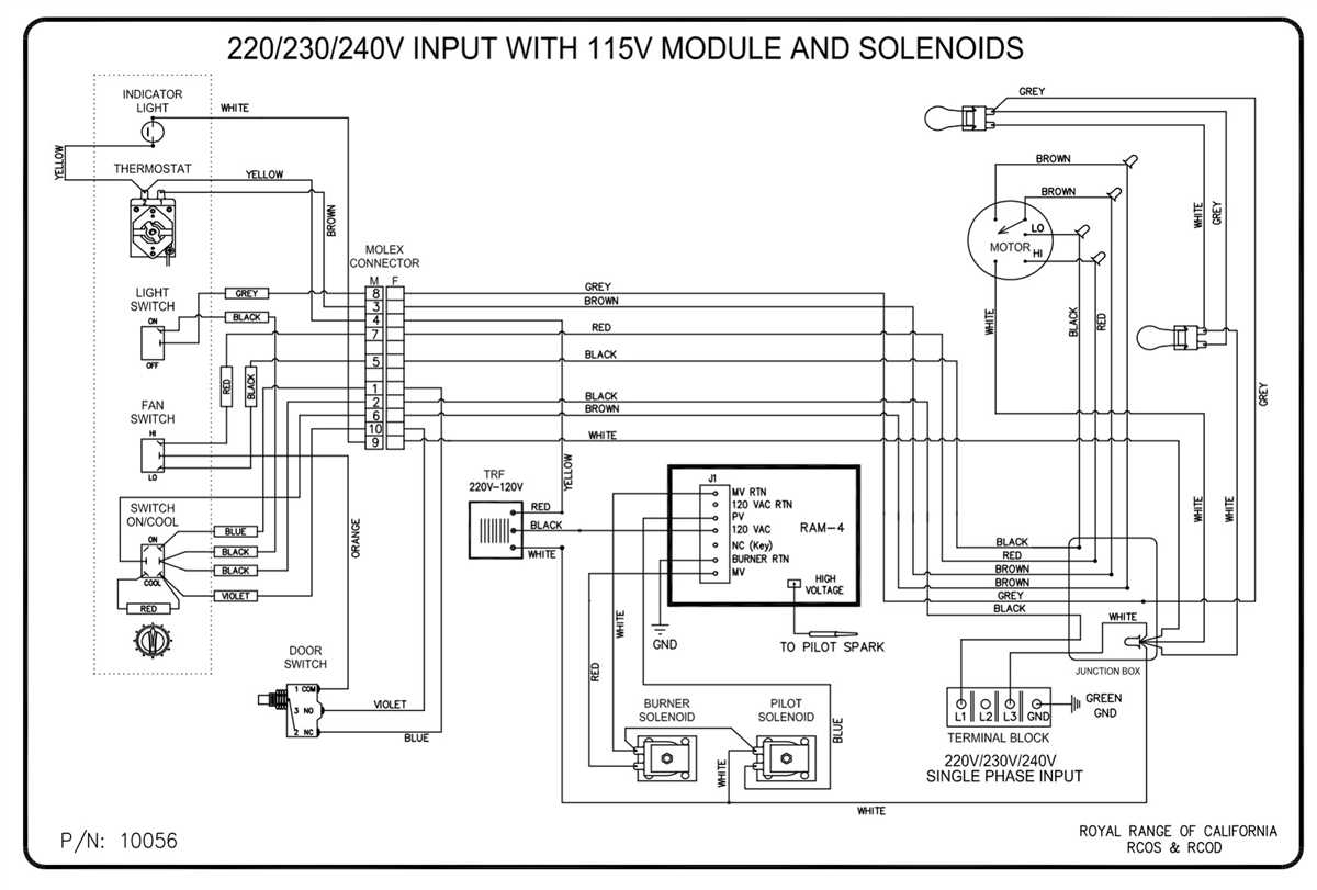
Another common wiring issue is damage to the wiring itself. Check the wiring for any signs of wear, fraying, or other damage. If you find any damaged wiring, it will need to be repaired or replaced. Damaged wiring can cause electrical shorts or loss of signal, so it is crucial to address this issue promptly.
3. Incorrect wiring placement
Incorrect wiring placement is another potential issue. Check the wiring diagram for your Compustar cm900as to ensure that all wires are connected to the correct terminals or components. Make sure that there are no cross-wired connections and that each wire is properly routed. Incorrect wiring placement can cause malfunctions or no operation at all, so it is important to double-check the wiring.
4. Faulty components
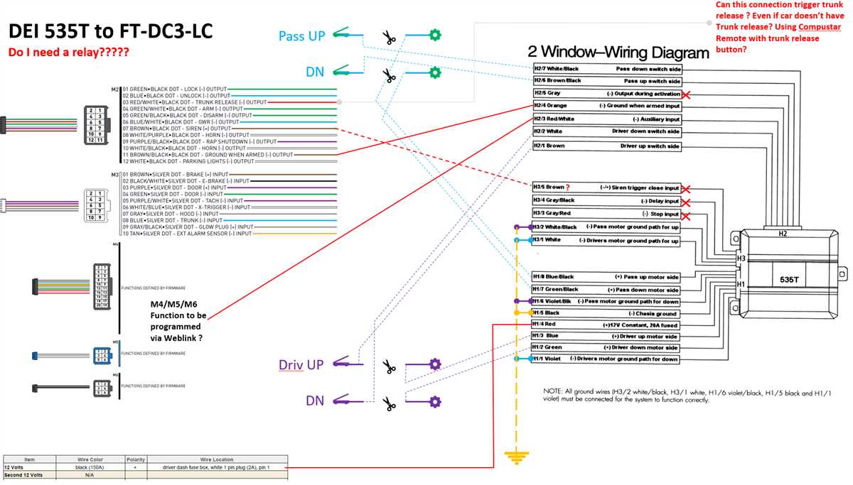
If you have checked all the wiring and connections and are still experiencing issues, it is possible that one of the components in your Compustar cm900as is faulty. In this case, you may need to replace the faulty component. Contact the manufacturer or a professional for assistance in identifying and replacing the faulty component.
By following these troubleshooting steps and solutions, you can resolve common wiring issues with your Compustar cm900as and ensure proper functionality. If you are unable to resolve the issue on your own, don’t hesitate to seek professional help to ensure the correct wiring and optimal performance.