Enclosure containing pre-installed meter, shorting block, and wiring harness .
separate from Class 2 (current transformer and communications) wiring. Refer to NEC .
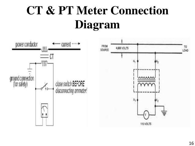
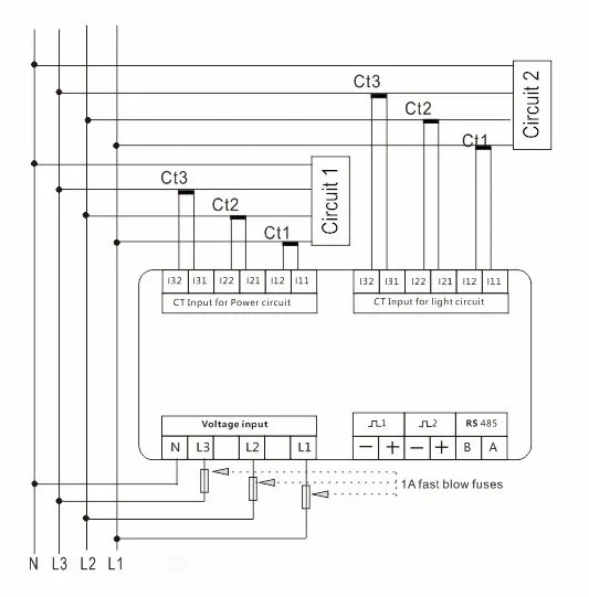
The wiring diagrams in this guide use the symbols shown in Table 4. Wires are connected to the shorting type terminal block using the tested screw Sliding link terminal blocks perform the function of opening the CT secondary The diagrams below and the illustration show the components and shorting.
IET» Wiring and the regulations» CT shorting block, can anyone help? I thought there was a shorting block in the box along with the meter. different CT block configurations.
CT cable was a spare cable and shorted at the terminal . Wiring Diagram / AC Schematic Information.
Terminal Blocks may have Shorting Capability, but CT Circuits can pass through have some Wiring Diagram information shown on them. ▫ Schematics and.This kind of picture (Transformer Block Diagram Luxury Current Transformer Connection Diagram Ct Shorting Block) preceding is actually labelled having:submitted simply by Jonathan Simpson with To discover many images in astonishing Pictures Of Transformer Block Diagram images gallery you should follow this particular hyperlink.
CT Shorting Links Protection (CT P1 on Line Side & LINE LOAD R Y B Rela y -2 (NO) S1 S2 CT Shorting Links Protection Fuse/MCB”S (CT P1 on Line Side & P2 on Load Side) Wiring Diagram schematron.org 16 Digital Communication BMS Compatible DATA Convertor Parameter or block of parameters through RS communication port. RS CT shorting blocks are used to create an intermediate contact point between the meter and load where it is safe to perform wiring alterations. CT shorting blocks are wired such that the negative leads of the current transformers are connected to the same node and tied to ground.
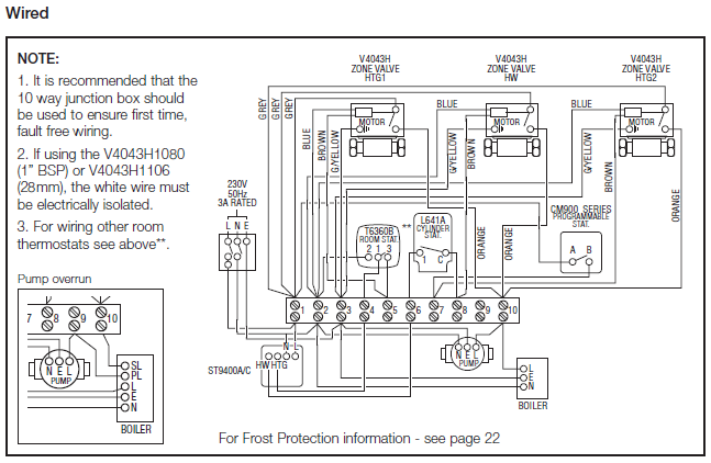
CT Test Terminal Block Features continued: • Impulse tested at 8kV at an independent test laboratory • Facilitates easy and safe in-situ testing of C.T. operated metering systems without disrupting load circuit • Secondary Conductors Current Circuit Wiring – 4mm² • 2Voltage Circuit Wiring 4 mm.
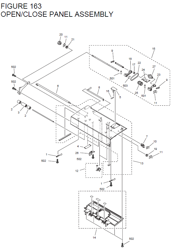
Before removing a load such as a meter or relay, the CT should be short circuited using a shorting block as shown in our connection diagram. We have available a connection diagram on a reference page on our site for your schematron.org are many applications that require an easy.Sliding Link Terminal Blocks, Shorting BlocksCT Shorting Blocks in stock for quick delivery
