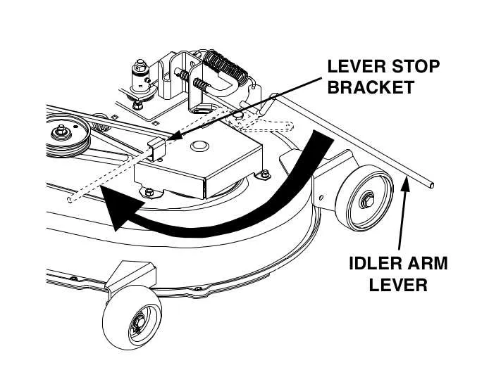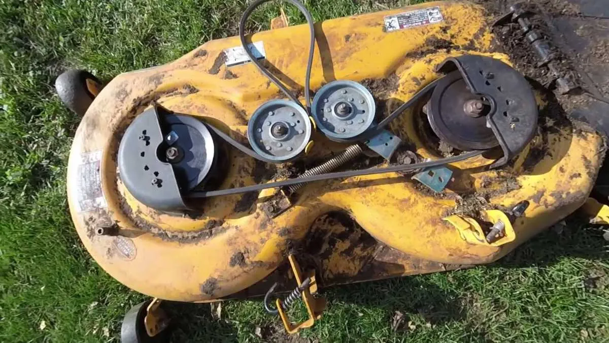
When dealing with lawnmowers and garden tractors, it’s crucial to understand the mechanics behind their power systems. The power transmission setup is essential for transferring engine power to accessories like mowers or snow blowers. If the system is malfunctioning, replacing or adjusting the drive mechanism may be necessary.
To identify any issues, start by checking the drive pulley system. This mechanism connects the engine’s power output to the components that engage the working tools. Look for wear or misalignment, as this can often cause performance issues.
In the process of inspecting the system, it’s helpful to refer to an accurate component layout. This reference will guide you in positioning the parts correctly, ensuring the power transmission system is functioning as it should. Accurate assembly can prevent unnecessary damage to the machinery.
If you’re replacing parts or conducting maintenance, ensure you use the correct specifications for each piece, as incorrect sizes or materials can lead to poor performance or even engine failure. Keeping the components clean and well-lubricated will also extend their lifespan.
Proper Installation of Power Take-Off System Components

Ensure accurate alignment when installing the drive components of the power take-off system. Misalignment can lead to excessive wear and malfunctioning of the rotating parts. Start by placing the primary pulley assembly correctly, ensuring it is tightly secured to prevent slippage.
Key tip: When positioning the rotation mechanism, double-check the tension of the moving parts to ensure they are neither too loose nor too tight. This will help optimize performance and prevent unnecessary strain on the system. If the tension is off, adjust the springs or reposition the components accordingly.
The mechanism’s routing must follow the exact sequence specified in the manufacturer’s instructions. Deviating from the recommended path can cause uneven power distribution and excessive friction. Pay close attention to the path of the rotating part as it feeds through pulleys to ensure everything moves smoothly without obstruction.
Note: Check periodically for wear on the components, especially after extended use. Worn-out parts should be replaced immediately to maintain optimal function and prevent further damage to the machine’s engine or related systems.
How to Identify the Correct Power Take-Off Drive Component
To ensure proper functionality of your machine, follow these steps to find the right power drive system component:
- Check the model and serial number of your equipment. This information is crucial to select the correct part. The model number can be found on the frame, usually near the rear or under the seat.
- Consult the manufacturer’s manual for specifications. The correct part is often listed by part number, which makes finding a suitable replacement easier.
- Measure the existing component if possible. Knowing the exact length, width, and thickness will help you find a compatible replacement that fits perfectly.
- Visit a certified dealer or trusted retailer. Provide the model details and ask for a compatible replacement based on the manufacturer’s guidelines.
- Inspect the wear pattern of the existing part. If you notice uneven wear or damage, the replacement should address these issues to prevent future failure.
Make sure to select a replacement with the same specifications as the original to avoid functional problems and ensure efficiency. Using parts from reputable sources guarantees compatibility and longevity.
Step-by-Step Guide to Install the PTO Drive System on Your Lawn Mower

Begin by disconnecting the spark plug wire to prevent accidental starting during the procedure. Raise the mower deck to give yourself ample space to work. Secure the deck in the raised position using the deck lift lever.
Next, remove any covers or shields blocking access to the drive system. These are typically located around the pulley and idler areas. Use a wrench to remove the screws securing the cover, then set it aside.
Locate the tensioning pulley and relieve the tension by rotating it counterclockwise. This will allow you to remove the drive component with ease. Be cautious as the spring may apply pressure during this step.
Once tension is released, carefully remove the existing drive component. Make sure to note the path it follows around the pulleys so you can correctly reinstall the new one. If the drive component is worn, replace it with a new one of the same specification.
Position the new part along the same routing path. Ensure the component follows the correct direction and aligns properly with the idler and drive pulleys. If needed, use the diagram of your mower’s pulley system to verify proper placement.
After placing the new part, rotate the tensioning pulley back into position to reapply tension. Confirm that the drive component is securely in place, and there is no slack.
Reinstall any shields or covers that were removed earlier, ensuring they are fastened tightly. Once everything is back in place, reconnect the spark plug wire.
Finally, test the mower by engaging the drive system and running it at a low speed. Listen for any unusual sounds, which could indicate improper installation or misalignment.
Common Drive System Issues and Troubleshooting Tips
Check for Slipping: If the machine isn’t engaging properly, the first thing to inspect is the tension in the drive system. If the components are loose or worn out, they may not engage with the required force. Tighten or replace the parts as needed to ensure the system functions smoothly.
Inspect for Fraying or Damage: Examine the components for visible wear. If they appear worn, cracked, or frayed, they should be replaced immediately. A damaged component will cause irregular movement or failure of the connected parts, leading to inefficient operation.
Monitor for Noisy Operation: Unusual noises can indicate an issue with the tensioners or pulleys. Inspect the tension mechanism to ensure it’s functioning correctly. If it’s loose or misaligned, adjust it to eliminate any abnormal sounds. Ensure pulleys are clear of debris and spinning freely.
Ensure Proper Alignment: Misalignment of the components can result in uneven wear or inefficient power transfer. Check the system for any misalignments and adjust accordingly. This will prevent premature wear and maintain peak performance.
Lubrication: Insufficient lubrication can lead to friction and premature damage. Regularly lubricate the system components to prevent overheating and reduce wear on moving parts. Use manufacturer-recommended lubricants to ensure compatibility with the materials involved.