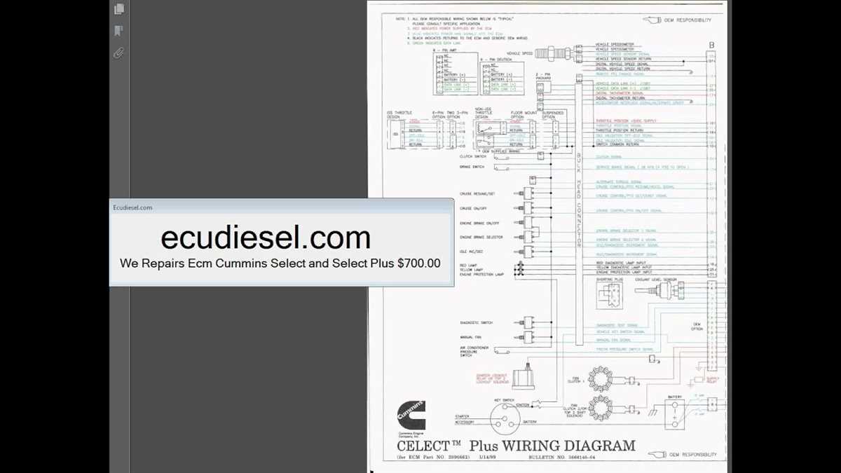
The Cummins N14 engine is a powerhouse in the world of heavy-duty diesel engines, known for its durability, reliability, and performance. One of the essential aspects of this engine is the sensor system, which plays a crucial role in monitoring and controlling various parameters of the engine.
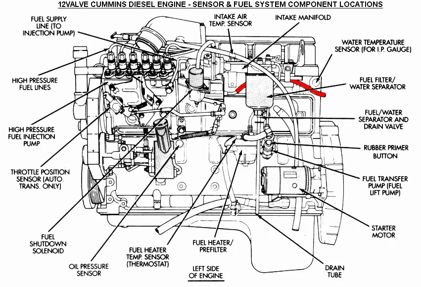
The sensor diagram of the Cummins N14 engine provides a comprehensive view of the various sensors installed in the engine. These sensors are responsible for measuring and transmitting vital information to the engine control module (ECM) to optimize fuel efficiency, emissions, and overall performance.
Some of the key sensors in the Cummins N14 engine include the coolant temperature sensor, oil pressure sensor, intake manifold pressure sensor, camshaft position sensor, crankshaft position sensor, and turbo boost pressure sensor. Each sensor has a specific function and is strategically placed to monitor the corresponding parameter accurately.
Understanding the sensor diagram of the Cummins N14 engine is crucial for diagnosing and troubleshooting any potential issues that may arise. By visually mapping out the sensor locations and understanding their functions, technicians can efficiently identify faulty sensors and address any performance or operational problems.
Cummins N14 Sensor Diagram: Everything You Need to Know
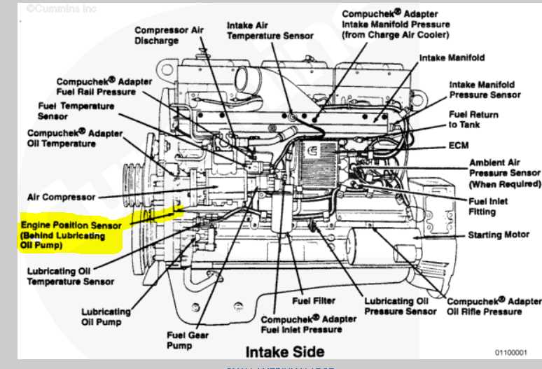
If you are working with a Cummins N14 engine, understanding its sensor diagram is crucial for troubleshooting and maintenance. The N14 engine is widely used in heavy-duty trucks and has several sensors that play a crucial role in monitoring and controlling various engine parameters. Here is everything you need to know about the sensor diagram of the Cummins N14 engine.
1. Coolant Temperature Sensor: The coolant temperature sensor is responsible for measuring the temperature of the engine coolant. It helps the engine control module (ECM) adjust the fuel injection timing and quantity based on coolant temperature, ensuring optimal performance and fuel efficiency.
2. Oil Pressure Sensor: The oil pressure sensor monitors the oil pressure in the engine. It sends signals to the ECM, which uses this information to activate warning lights or alarms if the oil pressure drops below a safe level. It is crucial for preventing engine damage due to low oil pressure.
3. Intake Manifold Air Temperature Sensor: This sensor measures the temperature of the air entering the engine’s intake manifold. The ECM uses this information to adjust the air-to-fuel ratio, ensuring optimal combustion and performance. The intake manifold air temperature sensor helps prevent engine overheating and helps in cold-start conditions.
4. Camshaft Position Sensor: The camshaft position sensor determines the position of the camshaft in relation to the crankshaft. This information is used by the ECM to control fuel injection timing and valve actuation. A faulty camshaft position sensor can cause issues with engine timing and affect overall performance.
5. Turbo Boost Pressure Sensor: The turbo boost pressure sensor measures the pressure of the air entering the engine through the turbocharger. The ECM uses this information to optimize turbocharger performance, ensuring efficient combustion and power output. A malfunctioning turbo boost pressure sensor can lead to decreased engine performance and potential turbocharger damage.
This is just a brief overview of some of the essential sensors in the Cummins N14 engine. It is vital to have a thorough understanding of the sensor diagram and their functions to diagnose and address any issues effectively. Regular maintenance and monitoring of these sensors can help ensure the smooth operation and longevity of your Cummins N14 engine.
Understanding the Cummins N14 Engine
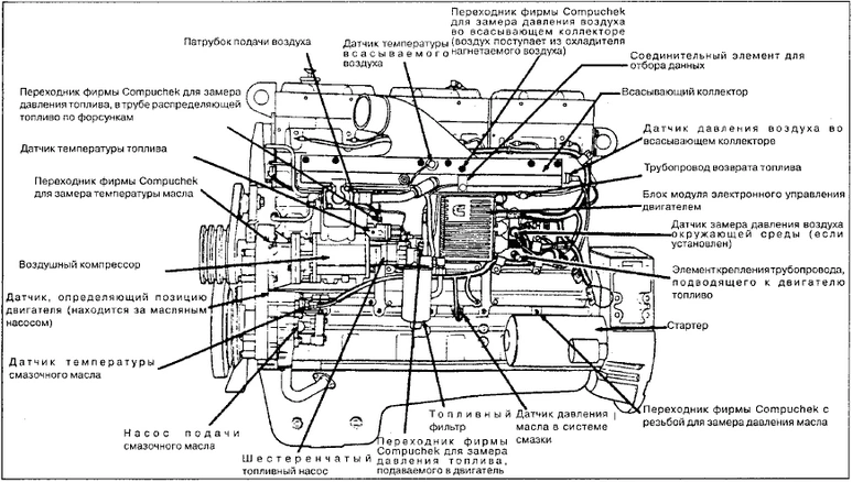
The Cummins N14 is a renowned engine model that has been widely used in a variety of applications, including heavy-duty trucks, buses, and construction equipment. It has gained a reputation for its durability, power, and reliability, making it a popular choice among many trucking fleets and operators.
One of the key features of the Cummins N14 engine is its electronic control system, which allows for precise fuel delivery and combustion control. This system includes a variety of sensors and components that work together to monitor and optimize engine performance. Some of the key sensors in the N14 engine include the coolant temperature sensor, oil pressure sensor, intake manifold pressure sensor, and turbocharger speed sensor.
The coolant temperature sensor is responsible for measuring the temperature of the engine coolant and providing this information to the engine control module (ECM). The ECM uses this data to adjust the fuel delivery and ignition timing to ensure optimal performance and efficiency. Similarly, the oil pressure sensor monitors the oil pressure level and alerts the ECM if it falls below or exceeds the recommended range, helping to prevent engine damage.
The intake manifold pressure sensor measures the pressure of the air entering the engine and provides this information to the ECM. This data is used to adjust the fuel injection timing and quantity, ensuring optimal combustion and power output. The turbocharger speed sensor monitors the speed of the turbocharger and helps optimize its operation, preventing over-speeding and potential damage.
In addition to these sensors, the Cummins N14 engine also features other components such as the camshaft position sensor, crankshaft position sensor, and fuel temperature sensor, which all contribute to the engine’s overall performance and efficiency. Understanding the role and functionality of these sensors and components is crucial in diagnosing and maintaining the Cummins N14 engine to ensure reliable and efficient operation.
Importance of Sensors in the Cummins N14 Engine
The Cummins N14 engine is a high-performance and reliable diesel engine widely used in heavy-duty trucks. One crucial component of this engine is the sensors that play a vital role in monitoring and controlling various parameters. These sensors provide real-time data to the engine control module (ECM), allowing it to make necessary adjustments for optimal engine performance.
One of the key sensors in the Cummins N14 engine is the temperature sensor. This sensor measures the temperature of coolant, oil, and air entering the engine. With this information, the ECM can adjust fuel delivery and timing to prevent overheating and optimize combustion efficiency. Another important sensor is the pressure sensor, which measures oil, fuel, and air pressure in the engine. By monitoring pressure levels, the ECM can ensure proper lubrication, fuel delivery, and air intake, preventing potential damage and improving overall engine performance.
In addition to temperature and pressure sensors, the Cummins N14 engine also relies on several other sensors, such as the speed sensor, position sensor, and oxygen sensor. The speed sensor provides information about the engine’s rotational speed, allowing the ECM to adjust fuel injection and timing accordingly. The position sensor detects the position of various engine components, such as the camshaft and crankshaft, enabling precise timing and synchronization. The oxygen sensor measures the level of oxygen in the exhaust gases, helping the ECM maintain the ideal air-to-fuel ratio for efficient combustion.
Overall, the sensors in the Cummins N14 engine are essential for ensuring optimal performance, fuel efficiency, and durability. By continuously monitoring critical parameters and providing real-time data to the ECM, these sensors enable accurate and timely adjustments to various engine functions. This leads to improved overall performance, reduced emissions, and extended engine life. Therefore, regular maintenance and replacement of faulty sensors are crucial to keep the Cummins N14 engine operating at its best.
Overview of the Sensor Diagram
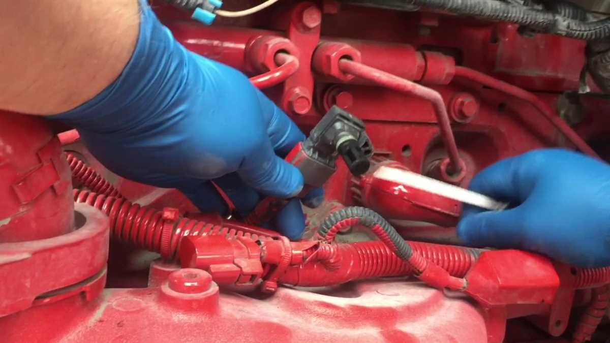
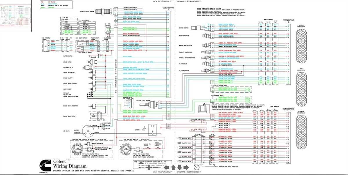
The Cummins N14 sensor diagram provides a visual representation of the various sensors used in the N14 engine. This diagram is a valuable tool for understanding the different components and the way they interact to monitor and control engine performance.
One of the main features of the sensor diagram is the identification of each sensor and its location within the engine. This information is crucial for technicians and mechanics when troubleshooting engine issues or performing routine maintenance. By knowing the location of a specific sensor, professionals can easily locate and inspect it for any signs of damage or malfunction.
The sensor diagram also illustrates the wiring connections between the sensors and the engine control module (ECM). This information helps technicians diagnose and repair any electrical issues that may affect sensor readings or prevent proper communication between the sensors and the ECM. By understanding the wiring connections, professionals can test and troubleshoot the electrical system more efficiently.
Additionally, the sensor diagram may include labels or descriptions for each sensor, indicating its function and purpose. This information is especially useful for technicians who may not be familiar with the specific sensors used in the Cummins N14 engine. By understanding the function of each sensor, professionals can quickly identify potential problems and make informed decisions regarding repairs or replacements.
In summary, the Cummins N14 sensor diagram is a valuable resource for technicians and mechanics working with this engine. It provides an overview of the sensors, their locations, and the wiring connections between them and the ECM. By utilizing this diagram, professionals can efficiently diagnose and repair engine issues, ensuring optimal performance and reliability.
Common Sensors in the Cummins N14 Engine
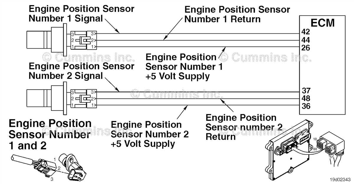
The Cummins N14 engine is equipped with a variety of sensors that monitor different aspects of the engine’s performance. These sensors play a crucial role in ensuring the engine runs efficiently and reliably. Here are some of the common sensors found in the Cummins N14 engine:
1. Coolant Temperature Sensor:
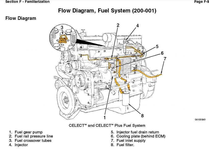
The coolant temperature sensor measures the temperature of the engine coolant. This information is used by the engine control module (ECM) to adjust the fuel injection and ignition timing for optimal performance. If the coolant temperature exceeds a certain threshold, the ECM may activate the engine protection features to prevent overheating.
2. Oil Pressure Sensor:
The oil pressure sensor monitors the oil pressure in the engine. It provides vital information to the ECM to ensure proper lubrication of the engine components. If the oil pressure drops below a safe level, the ECM may trigger a warning light or activate the engine protection features to prevent engine damage.
3. Crankshaft Position Sensor:
The crankshaft position sensor detects the position and speed of the crankshaft. This information is used by the ECM to determine the timing of fuel injection and ignition. It is also used for diagnostics, such as detecting misfires and engine speed calculation.
4. Boost Pressure Sensor:
The boost pressure sensor measures the pressure of the intake air after the turbocharger. It provides information to the ECM for controlling the boost level and optimizing the air-fuel mixture. The boost pressure sensor is essential for ensuring proper engine performance and fuel efficiency.
5. Exhaust Gas Temperature Sensor:
The exhaust gas temperature sensor measures the temperature of the exhaust gases. This information is used by the ECM to monitor the efficiency of the combustion process and the performance of the emissions control system. If the exhaust gas temperature exceeds safe limits, the ECM may take corrective action to prevent engine damage.
Overall, these sensors in the Cummins N14 engine work together to provide accurate and real-time data to the ECM, allowing for precise control and optimal performance of the engine.
Troubleshooting Sensor Issues in the Cummins N14 Engine
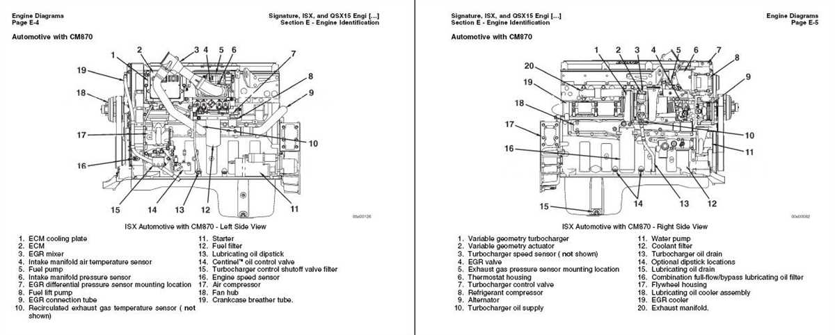
Sensors play a crucial role in the performance and efficiency of the Cummins N14 engine. They provide important data to the engine control module (ECM) for proper operation and optimization. However, sensor issues can arise, causing potential problems with engine performance. Understanding how to troubleshoot sensor issues in the Cummins N14 engine is essential for maintaining optimal engine performance.
1. Check sensor connections: One of the first steps in troubleshooting sensor issues is to check the sensor connections. Ensure that all sensors are properly connected and securely plugged into their respective connectors. Loose or damaged connections can lead to faulty sensor readings.
2. Inspect sensor wiring: In addition to checking the connections, inspect the sensor wiring for any signs of damage, such as frayed wires or exposed connections. Damaged wiring can disrupt the flow of sensor data and result in inaccurate readings. Repair or replace any damaged wiring as necessary.
3. Clean or replace sensors: Sensors can become dirty or contaminated over time, affecting their accuracy. Use a gentle cleaning solution and a soft brush to clean the sensors, being careful not to damage any delicate components. If cleaning doesn’t resolve the issue, it may be necessary to replace the sensor altogether.
4. Use diagnostic tools: Utilize diagnostic tools designed for the Cummins N14 engine to identify specific sensor issues. These tools can provide real-time readings and pinpoint any sensor-related problems. By using diagnostic tools, technicians can quickly identify and resolve sensor issues, minimizing downtime and maximizing engine performance.
5. Consult the engine service manual: When troubleshooting sensor issues, refer to the engine service manual for detailed information and guidelines specific to the Cummins N14 engine. The service manual will provide instructions for testing and diagnosing sensor problems, as well as recommendations for sensor replacement, if necessary.
By following these troubleshooting steps and utilizing the appropriate resources, technicians can effectively diagnose and resolve sensor issues in the Cummins N14 engine. Regular maintenance, including regular inspection and cleaning of sensors, can also help prevent future sensor problems and ensure optimal engine performance.
Maintenance Tips for Sensors in the Cummins N14 Engine
Sensors play a crucial role in the performance and efficiency of the Cummins N14 engine. Regular maintenance of these sensors is essential to ensure accurate readings and prevent potential issues. Here are some maintenance tips to keep in mind:
- Clean regularly: Sensors can accumulate dirt, oil, or other debris, affecting their performance. Regularly check and clean the sensors to remove any buildup or contamination. Use appropriate cleaning materials and techniques recommended by Cummins.
- Inspect for damage: Check for any signs of physical damage or wear on the sensors. Look for cracks, corrosion, or loose connections. If any damage is found, replace the sensor immediately to prevent further issues.
- Monitor sensor readings: Keep an eye on the sensor readings through the engine’s diagnostic system. Any unusual or inconsistent readings may indicate a problem with the sensor. Investigate and address the issue promptly to prevent additional damage.
- Check wiring and connectors: Ensure that the wiring and connectors of the sensors are in good condition. Loose or damaged connections can disrupt the sensor’s signal and affect its performance. Regularly inspect and repair any issues with the wiring and connectors.
- Follow recommended maintenance schedule: Cummins provides a maintenance schedule for their engines, including sensor inspections and replacements. Follow the recommended maintenance schedule to ensure optimal performance and longevity of the sensors.
By following these maintenance tips, you can ensure that the sensors in your Cummins N14 engine continue to provide accurate data and contribute to the engine’s overall performance. Regular monitoring, cleaning, and inspection will help prevent potential issues and extend the lifespan of the sensors, ultimately saving you time and money in the long run.