
Element diagrams are graphical representations of the elements found on the periodic table. These diagrams provide a visual way to organize and understand the properties of each element. They display information such as atomic number, atomic mass, and group number, allowing scientists to quickly identify and compare different elements.
One of the key features of an element diagram is the labeling of each element. This labeling includes the element’s symbol and atomic number, which are displayed in a clear and concise manner. The symbol is typically a one- or two-letter abbreviation for the element, such as H for hydrogen or Fe for iron. The atomic number is a unique identifier for each element, representing the number of protons in an atom’s nucleus.
Element diagrams are used in a variety of scientific fields, including chemistry and physics. They are essential tools for researchers and educators alike, providing a visual representation of the periodic table and helping to explain the relationships between different elements. By studying and analyzing these diagrams, scientists can gain a deeper understanding of the properties and behaviors of various elements, leading to new discoveries and advancements in the field.
What is an Element Diagram?
An element diagram is a visual representation of the elements that make up a system or entity. It is commonly used in software engineering and system design to depict the structure and relationships between different components of a system. This diagram helps in understanding the composition and organization of the system, facilitating communication and decision-making during the design and development process.
The key components of an element diagram include:
- Elements: These are the fundamental building blocks or entities of the system. They can be tangible objects, classes, modules, or subsystems, depending on the level of abstraction.
- Relationships: The connections or associations between elements are represented by labeled lines or arrows. These relationships can be of various types, such as dependency, composition, inheritance, or association, and they convey how elements interact and collaborate within the system.
- Properties: Each element may have associated attributes or properties that provide additional information about them. These properties can be depicted as key-value pairs or as a separate section within the diagram.
An element diagram is typically created using specialized modeling tools or software, which provide a range of symbols, shapes, and notation conventions to represent different types of elements and relationships. The diagram can be as simple as a high-level overview or as detailed as a comprehensive representation of the entire system architecture, depending on the specific needs of the design process.
In conclusion, an element diagram is a valuable tool for visualizing and documenting the structure and relationships within a system. It aids in understanding the composition and behavior of the system’s components, facilitating effective communication and decision-making during the design and development phases.
Importance of Labeled Element Diagrams
Element diagrams are a crucial visual representation tool used in various fields, including chemistry, biology, and physics. These diagrams allow researchers, scientists, and students to understand the composition, structure, and relationships between different elements or components within a system. Labeled element diagrams are especially important as they provide clear and concise information about the individual elements and their specific roles within the larger context.
One of the main advantages of labeled element diagrams is their ability to simplify complex information. By clearly labeling each element or component within the diagram, it becomes much easier for individuals to identify and understand their respective functions and interactions. This is particularly useful in educational settings, where students can quickly grasp the concepts being taught and apply them to real-world scenarios.
Furthermore, labeled element diagrams promote accurate communication and collaboration among researchers and scientists. When working on projects or conducting experiments, it is crucial to have a common language that ensures everyone is on the same page. By using labeled element diagrams, researchers can effectively communicate complex concepts and share information with their peers, facilitating a more efficient and productive work environment.
Another significant benefit of labeled element diagrams is their use in problem-solving and analysis. Whether it is analyzing a chemical reaction, studying cellular processes, or understanding the behavior of physical systems, labeled element diagrams allow scientists to visually break down complex phenomena into smaller, more manageable components. This facilitates a systematic approach to problem-solving and helps identify key relationships and patterns that may not be immediately apparent.
Overall, labeled element diagrams play a crucial role in various disciplines by providing a visual representation of complex systems, facilitating understanding, promoting accurate communication, and enhancing problem-solving capabilities. They are an invaluable tool for researchers, scientists, and educators alike, enabling them to explore and comprehend the intricacies of the natural world.
How to Create an Element Diagram?
Creating an element diagram is a crucial step in visualizing the structure and relationships of elements in a system or project. By mapping out the elements and their connections, you can gain a better understanding of how they interact and function as a whole.
To create an element diagram, follow these steps:
- Identify the elements: Begin by identifying the key elements or components of the system. These could be physical entities, processes, data, or any other relevant element.
- Label the elements: Once the elements are identified, label them accordingly. Use concise and descriptive names to clearly represent each element.
- Define relationships: Determine the relationships between the elements. These relationships could be hierarchical, sequential, or even interconnected.
- Create connections: Draw arrows or lines to represent the connections between the elements. This will help visualize the flow or dependencies between different components.
- Add details: Include additional details or attributes for each element, if necessary. This could involve specifying properties, functions, or any other relevant information.
- Organize the diagram: Arrange the elements in a logical and structured manner. Group related elements together to make the diagram more readable and intuitive.
- Review and refine: Once the diagram is complete, review it for accuracy and clarity. Make any necessary revisions or adjustments to ensure that the diagram accurately represents the intended system or project.
Overall, creating an element diagram is an essential tool for visualizing and communicating the structure of a system. It allows for a better understanding of element relationships and can aid in the design and development process.
Commonly Used Labels in Element Diagrams
Element diagrams are a visual representation of elements and their relationships in a system or process. These diagrams are commonly used in various fields, such as software development, business analysis, and system design. To effectively communicate information, element diagrams often use labels to identify different components and their characteristics. Here are some commonly used labels in element diagrams:
1. Name: The name label is used to identify the element or component in the diagram. It provides a clear and concise way of referring to the element throughout the diagram and documentation.
2. Type: The type label describes the category or classification of the element. It helps to organize and group elements based on their characteristics or properties. For example, in software development, types can include classes, interfaces, or data types.
3. Attributes: Attributes are properties or characteristics of an element that provide additional information. These labels can be used to specify details about an element, such as its size, color, or behavior. Attributes can help in understanding the behavior and functionality of an element in the system.
4. Relationships: Relationships labels are used to illustrate the connections and associations between elements. These labels can indicate dependencies, associations, or dependencies between elements in the diagram. They help in visualizing the interactions and dependencies within the system.
5. Multiplicity: Multiplicity labels represent the cardinality or quantity of relationships between elements. They indicate how many instances of one element can be associated with another. Multiplicity labels can be used to define constraints and restrictions on the relationships between elements.
6. Stereotypes: Stereotypes are labels that provide additional meaning or context to an element. They can be used to indicate if an element is a specific type, such as an abstract element, an interface, or a database table. Stereotypes help in understanding the role or purpose of an element in the system.
These are just a few examples of commonly used labels in element diagrams. The specific labels used in a diagram may vary depending on the context and purpose of the diagram. However, these labels provide a foundation for effectively communicating information about elements and their relationships in a visual manner.
Interpreting an Element Diagram
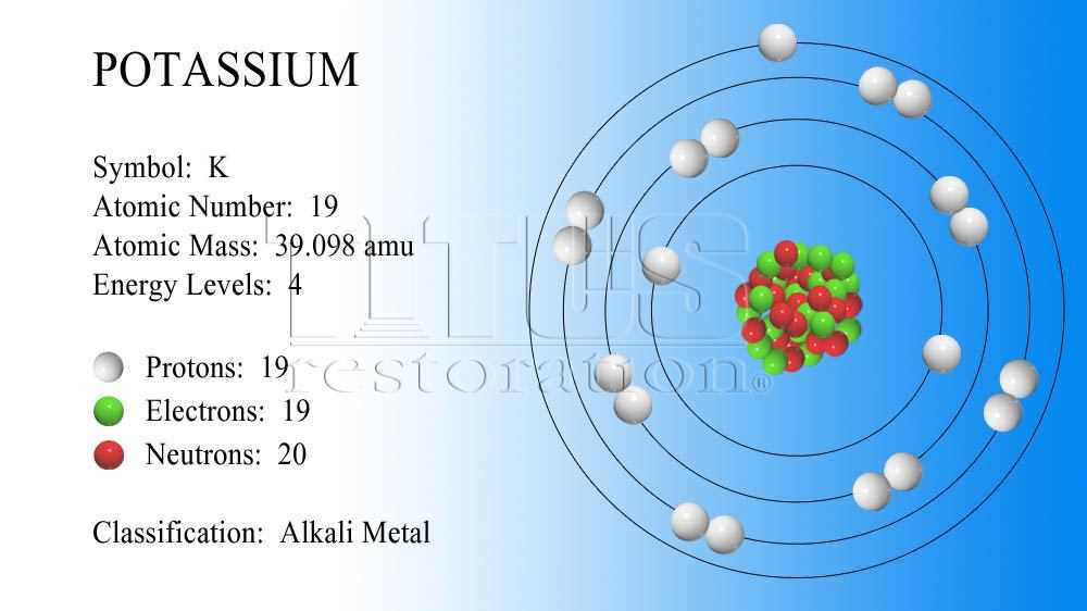
When it comes to understanding the composition and structure of different elements, an element diagram can be a valuable tool. An element diagram is a visual representation of an element’s atomic structure, showing the arrangement of protons, neutrons, and electrons within the atom. By examining an element diagram, scientists can gain important insights into an element’s properties and behavior.
Atomic Number and Symbol: One of the key components of an element diagram is the atomic number and symbol. The atomic number represents the number of protons in an atom’s nucleus, while the symbol is a shorthand way of indicating the element. For example, the element diagram of carbon would show the atomic number 6 and the symbol C.
Electron Configuration: Another important aspect of an element diagram is the electron configuration. Electrons are arranged in shells or energy levels around the nucleus. The electron configuration provides information about how the electrons are distributed among these shells. The diagram typically shows the number of electrons in each shell, ranging from the innermost shell (closest to the nucleus) to the outermost shell.
Isotopes: An element diagram may also indicate the presence of isotopes. Isotopes are atoms of the same element that have different numbers of neutrons in their nucleus. The diagram may show different isotopes by including their mass number, which is the total number of protons and neutrons. This can be useful in understanding variations in the atomic mass of an element.
Nuclear Notation: Some element diagrams may include nuclear notation, which provides additional information about the element’s isotopes. Nuclear notation consists of the element’s symbol, followed by the mass number as a superscript and the atomic number as a subscript. For example, the nuclear notation for carbon-14 would be C-14.
In conclusion, an element diagram serves as a visual representation of an element’s atomic structure and provides important information about its composition and behavior. By understanding the key components of an element diagram, scientists can gain valuable insights into the properties and characteristics of different elements.
Conclusion
Element diagrams are an important tool in various scientific fields for understanding the organization and properties of elements. By visually representing the atomic structure, electron configuration, and other key characteristics of elements, these diagrams provide a concise and systematic way to study and analyze chemical elements.
Element diagrams are commonly used in chemistry education to teach students about the periodic table and its significance. They help students visualize the arrangement of elements, understand their atomic properties, and predict their reactivity. Additionally, element diagrams are extensively used in materials science and engineering to study the behavior of elements in different conditions, such as high temperature or pressure.
Overall, element diagrams play a crucial role in enhancing our understanding of the elements and their properties. They provide a visual representation that simplifies complex concepts and facilitates learning and analysis. Whether in educational settings or research laboratories, element diagrams are a valuable tool for scientists, engineers, and students alike.
Q&A:
What are element diagrams?
Element diagrams are visual representations that show the arrangement of elements within a system or process. They are commonly used in various fields such as chemistry, physics, and engineering to illustrate the components and their relationships.
What are some applications of element diagrams in chemistry?
In chemistry, element diagrams are often used to depict the periodic table, which shows the arrangement of elements based on their atomic number and chemical properties. These diagrams are also useful for illustrating chemical reactions, electron configurations, and molecular structures.
How are element diagrams used in physics?
In physics, element diagrams are commonly used to illustrate the composition of materials, such as alloys or semiconductors. These diagrams can show the arrangement of atoms within a crystal lattice, helping researchers understand the physical properties and behavior of different materials.
What are some applications of element diagrams in engineering?
In engineering, element diagrams are used to visualize the arrangement of components within a system, such as electrical circuits or mechanical assemblies. These diagrams can help engineers analyze and optimize the design, identify potential bottlenecks or failures, and communicate ideas effectively.