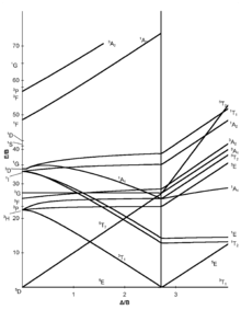
in the Tanabe-Sugano diagrams for the d6 electron configuration of octahedral complexes. The error arises with the free ion term giving rise to the strong-field.

Explanation about the different energy levels in the diagram. ..
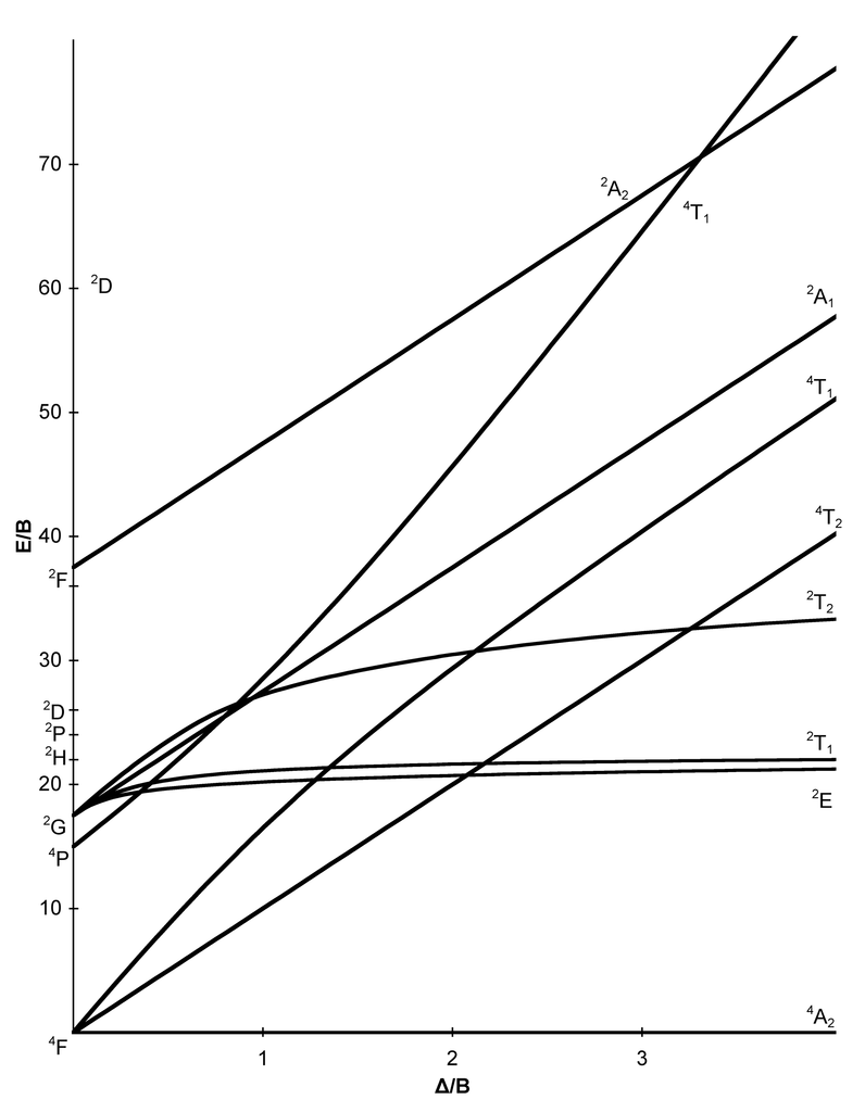
Fig Tanabe-Sugano diagram for d6 octahedral complex. Page 9 of Joint Initiative .
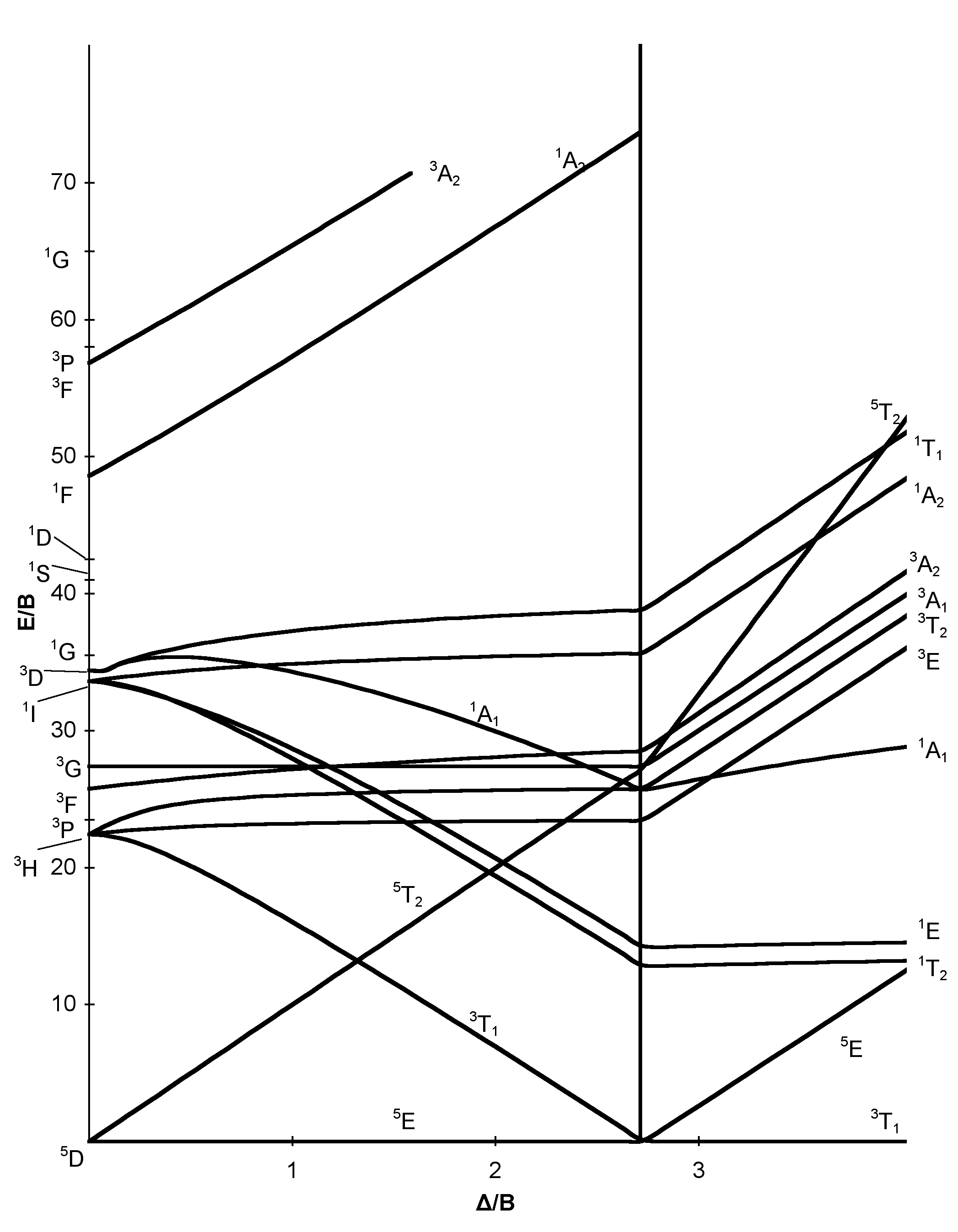
Tanabe–Sugano diagrams are used in coordination chemistry to predict absorptions in the UV, . d6 Tanabe-Sugano diagram.
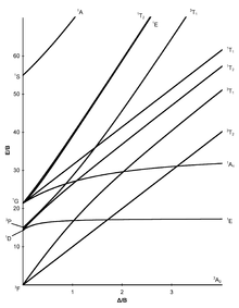
d6 electron configuration. Coordination Chemistry III: Tanabe-Sugano Diagrams and Charge Transfer.
Chapter 11 extra material (to finish Chapter 11). It is recommended to name the SVG file “D6 Tanabe-Sugano schematron.org” – then the template Vector version available (or Vva) does not need.Title: Microsoft PowerPoint – handout6b Author: Alan Jircitano Created Date: 11/22/ PM.
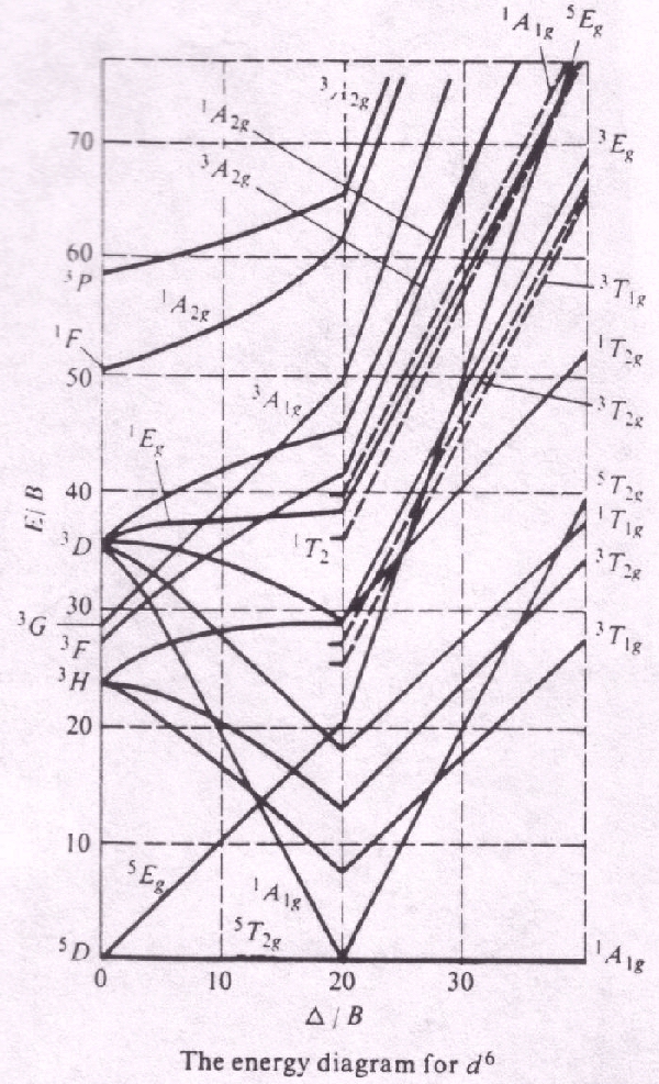
Tanabe–Sugano diagrams are used in coordination chemistry to predict absorptions in the UV, visible and IR electromagnetic spectrum of coordination schematron.org results from a Tanabe–Sugano diagram analysis of a metal complex can also be compared to experimental spectroscopic data. Lecture 4 May Tanabe Sugano Diagrams A Tanabe-Sugano (TS) diagram plots the energy dependence of the various ligand field states (or terms) with field strength. The strength of the ligand field is defined by Dq, which is related to the octahedral crystal field splitting by 10Dq = ∆o.
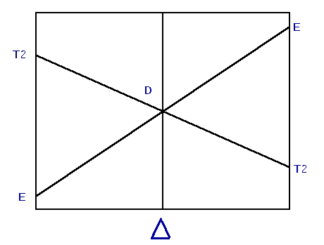
The energy of the state is given by E. The baseline in the Tanabe-Sugano diagram represents the lowest energy or ground term state.
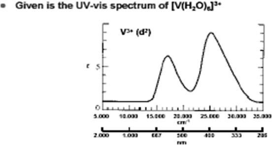
The d 2 case (not many examples documented). The electronic spectrum of the V 3+ ion, where V(III) is doped into alumina (Al 2 O 3), shows three major peaks with frequencies of: ν1= cm-1, ν2= cm-1 and ν3= cm 3 Tanabe-Sugano diagrams This diagram results when the energy of various terms are plotted against B, where B is the Racah arameter (ip nterelectronic repulsion parameter).Tanabe–Sugano diagram – Wikipediad6 low spin Tanabe-Sugano diagram
