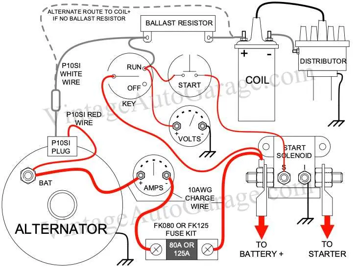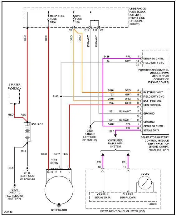
For efficient and safe installation of a 4-wire electrical charging system, start by understanding the function of each terminal. The most critical connections include the output terminal, the ground, the sense terminal, and the field control terminal. Each of these plays a vital role in ensuring the correct voltage is produced and regulated.
1. Output Terminal: Connect this to the main power distribution bus, ensuring that your electrical system receives the full voltage output from the generator. Proper connection here prevents overloads and ensures stable performance across the entire system.
2. Ground Terminal: This must be securely attached to a clean metal surface. A poor ground connection can lead to inconsistent charging, electrical spikes, or even system failure.
3. Sense Terminal: The role of the sense terminal is to monitor system voltage. It should be wired directly to the battery or another critical power source to detect voltage fluctuations. Any issues with this terminal will prevent the system from accurately adjusting the charging rate.
4. Field Control Terminal: This terminal regulates the excitation current. It can be connected to an external control unit or voltage regulator, which controls the generator’s output according to the system’s demands. A malfunction here will lead to overcharging or undercharging, potentially damaging sensitive components.
Ensure all connections are tightly secured and insulated to avoid shorts and signal interference. For optimal performance, regularly check the system for any signs of wear or corrosion on the connectors. Properly maintaining each terminal will extend the life of your electrical system and improve its efficiency.
4-Wire Connection Setup for GM Charging System
For proper connection, ensure that the four terminals on the generator are correctly identified and linked to their respective components. The primary output terminal should be connected to the positive battery terminal to ensure the system delivers power to the electrical load. A secondary terminal is for the sensing wire, which connects to a point on the vehicle’s electrical system where the voltage is monitored. The third terminal is used for the ground, completing the circuit and stabilizing the operation. The fourth terminal manages the signal that regulates the charge rate, typically routed through the voltage regulator to adjust as needed.
Ensure all terminals are securely connected to avoid fluctuating power or system damage. If you notice irregular charging behavior, double-check the connections and ensure proper grounding. The system will operate most efficiently when all four connections are stable and free from corrosion or wear.
Understanding the Wiring Colors and Their Functions

The color coding of the four connections is essential for proper installation and maintenance. Here’s a breakdown of the colors and their respective purposes:
1. Black or Brown Wire: Typically represents the ground connection. This is the reference point for the entire system, ensuring the current flows correctly to the vehicle’s chassis or battery negative terminal.
2. Red or Orange Wire: This is the main power output line, providing charging current to the battery. It connects directly to the battery positive terminal, delivering the regulated voltage from the charging system.
3. Green or Yellow Wire: Used for voltage sensing. This wire monitors the voltage level and helps control the charging rate by communicating with the regulator. Proper function ensures that the battery is charged within the correct voltage range.
4. Blue or White Wire: This is typically the exciter or trigger wire, activating the system. It connects to the ignition switch or alternator’s control unit, initiating the charge process once the engine starts running.
Correctly identifying and connecting these lines is crucial for the efficiency of the charging process and avoiding electrical failures.
Step-by-Step Guide to Proper Wiring Connections

To ensure reliable operation and optimal performance of your electrical system, follow these steps carefully when making connections:
- Identify the Terminal Points: Locate the key connection points. These usually include the main power input, the ground, the sensing terminal, and the excitation terminal. Proper identification of these will prevent incorrect hookups.
- Connect the Main Power Lead: Start with the heavy-duty cable that links the charging system to the battery. Securely fasten the positive terminal to the designated power port. Ensure a solid connection to avoid potential voltage drop.
- Grounding the System: Connect the ground cable from the system to a clean, unpainted metal surface on the engine block or chassis. A poor ground can lead to malfunctions and erratic performance.
- Voltage Sensing Terminal: This terminal controls the system’s voltage regulation. Attach a wire from the sensing terminal to the battery or the fuse block. Ensure the wire is routed securely to avoid damage.
- Excitation Circuit: Connect the excitation lead to the ignition or accessory switch, depending on the design of your vehicle. This activates the charging system when the engine is started.
After making these connections, double-check each to ensure there are no loose or exposed wires. Proper insulation is crucial for safety and functionality. Once connected, test the system by running the engine and checking the voltage output to verify everything is functioning correctly.
Troubleshooting Common Electrical Connection Problems in 4-Pin Charging Systems
If the charging system isn’t functioning, start by inspecting the output lead for any signs of corrosion or damage. Ensure it’s securely connected to the battery’s positive terminal. Loose or worn connections can lead to low voltage or charging failures.
The second pin, typically responsible for voltage sensing, should be firmly attached to the vehicle’s fuse panel. A poor contact here can result in erratic or inadequate charging, often showing as fluctuating voltage readings on the dashboard.
Next, check the ground connection. A weak ground can lead to poor performance or complete failure of the electrical unit. Make sure that the ground strap is clean, free of rust, and tightly fastened to a solid part of the engine block or frame.
Lastly, the excitation wire, which energizes the system, often malfunctions due to a faulty regulator or broken connection. Test for continuity with a multimeter, and if there’s no voltage signal when the engine is running, the regulator may need replacement.