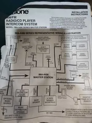
Use terminal A to connect the master station to remote speakers. This ensures consistent signal distribution across all locations. Pay attention to polarity–reversed wiring on terminals A and B will disrupt intercom functionality.
Power input is routed through terminals marked T1 and T2. These should be linked to a 16V AC transformer rated at a minimum of 30VA. Avoid using DC adapters, as they may cause system instability or permanent damage.
Speaker loop connections should be made using 18 AWG twisted pair. Keep cable runs under 150 feet to reduce line loss. If interference is present, switch to shielded cable and ground the shield only at the central unit.
Door release mechanism connects to terminals C and D. These must interface with a normally open relay rated for 24V. Use momentary push-button controls to avoid continuous current flow through the latch solenoid.
For optional music input, use the AUX-IN pins found on the lower edge of the control board. Input level should not exceed 500mV RMS. Overvoltage may trigger the auto-mute feature, cutting audio to all connected zones.
Wiring Layout and Terminal Functions
Start by identifying the main board connections on the master intercom unit. Use the following terminal references for accurate setup:
- TB1: Main power input – connect to a 16V AC transformer.
- TB2: Door speaker wiring – pins marked “D1” and “D2”. Ensure correct polarity to avoid distorted audio.
- TB3: Room station outputs – labeled 1 through 9. Each pin corresponds to a specific substation location.
- TB4: Music input – link to auxiliary audio source via shielded cable to reduce interference.
Fuse rating is 1A slow-blow, located beside the transformer input. Replace only with same specification. Volume adjustments are managed via onboard potentiometers marked “M” (music), “I” (intercom), and “T” (tone). Avoid over-rotating to prevent signal clipping.
Door release is controlled by relay output “DR”. This terminal triggers a low-voltage strike when a call is accepted from the entry point. Wire it using 18AWG cable for distances up to 50 feet. For longer runs, increase wire gauge accordingly.
Always disconnect AC power before making changes to internal wiring. Refer to model-specific pinouts printed directly on the rear casing.
Wiring connections for door speaker and remote stations

Connect terminal T1 on the master unit directly to one side of each door speaker and all remote units using 3-conductor cable. This line provides power and audio signaling. Maintain polarity throughout to prevent audio distortion.
Use terminal T2 to complete the circuit with the remaining side of each station. Ensure continuity by daisy-chaining this terminal from one location to the next.
Terminal B should be linked to the common wire in all remote locations. This line supports call signal functions and must remain isolated from T1 and T2 lines to avoid short circuits.
For outdoor door speaker units, use weather-resistant wiring and include a gasketed mounting box. Route wires through conduit where exposure is likely.
Check impedance compatibility: speakers must match the rated output of the master control to avoid overload or underperformance. Avoid splicing wires without proper connectors to maintain audio clarity.
Label each wire clearly during installation and verify with a multimeter before powering on the system. Consistent wire color coding is critical during troubleshooting or future expansion.
Power supply layout and voltage requirements
Use a dedicated 16V AC transformer rated at no less than 30VA to ensure stable operation. Connect the transformer’s output leads directly to terminals marked “T1” and “T2” on the central control unit. Avoid sharing this transformer with other devices to prevent voltage drops under load.
Maintain wire runs under 100 feet using 18 AWG copper conductors to minimize resistance. For longer distances, upgrade to 16 AWG. Confirm that all connections are secure and free of corrosion, particularly at terminal screws and spade connectors.
The main board requires a constant 16V AC input; any deviation below 14V under load may cause system instability. Ensure the transformer is mounted in a ventilated location and not enclosed in a wall cavity. Use a voltmeter to verify output voltage at the terminal block after installation.
Replacement Strategy Using Original IM3003 Wiring Layout
Always refer to the authentic wiring schematic when replacing components to ensure exact match of wire colors and terminal connections. Cross-check each lead against the original blueprint to avoid mismatches that can cause malfunctions or damage.
Begin by disconnecting power and labeling all wires according to their position and function shown in the factory electrical map. Use a multimeter to verify continuity and confirm wire roles before detaching any connectors.
When substituting parts, follow the established circuit pathways and preserve original wire gauges. Avoid splicing or rerouting cables unnecessarily to maintain system integrity and reduce electrical noise or interference.
Test each stage of the unit after reassembly, verifying voltages align with the initial wiring reference. If discrepancies occur, revisit connections step-by-step using the authentic layout as your guide.
Document any modifications with clear notes and updated sketches to facilitate future maintenance and avoid confusion in subsequent repairs.