Start by ensuring you have a solid understanding of the power requirements for your emergency equipment. For most setups, a direct connection to the vehicle’s power source is necessary, with proper fuses and a reliable ground connection. Avoid using existing vehicle circuits that may not handle the additional load, as this could cause malfunction or even damage.
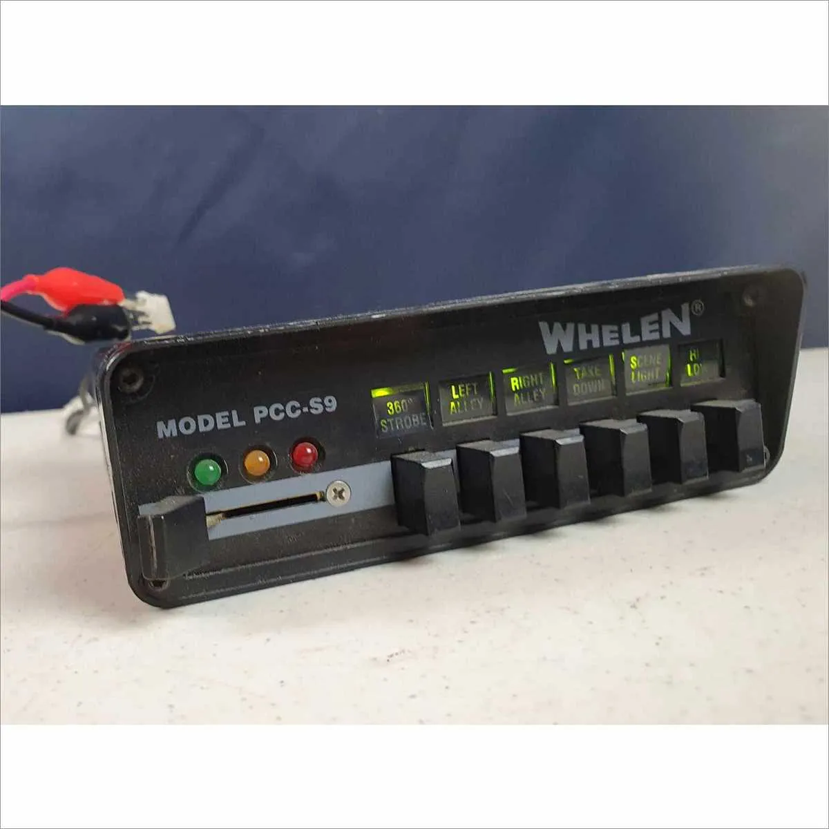
Next, connect the control switches to the main unit, ensuring they are wired correctly for switching the various patterns and functions. Depending on the model, you may need to account for multiple outputs, such as strobes or steady lights, which should be routed to separate channels to avoid interference.
For the most efficient installation, keep your wiring as short as possible while avoiding tight bends that could damage the cables. Use high-quality, weather-resistant connectors to prevent corrosion and ensure long-term reliability. Pay close attention to polarity when connecting the power cables, as incorrect connections can cause malfunction or even permanent damage to the system.
Finally, confirm that all safety protocols are followed, including securing the wires in place to prevent any accidental disconnections during operation. After testing, check all components for any signs of overheating or malfunction before finalizing the setup.
Wiring Overview for Emergency Vehicle Signal Systems

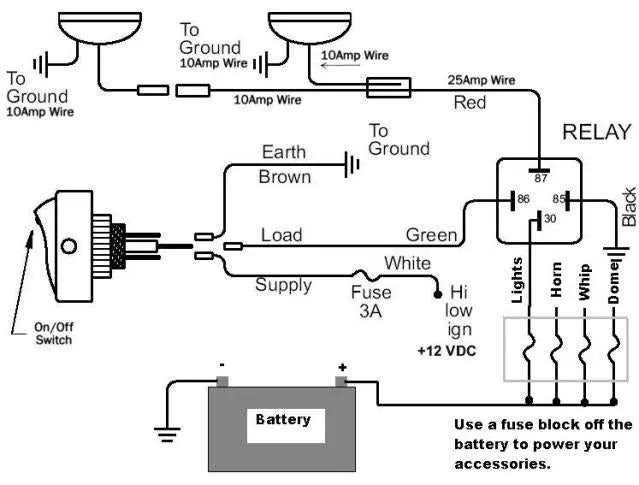
To install an emergency vehicle signaling system, ensure proper connections between the power source, control switch, and the light module. First, connect the positive terminal of the power supply to the designated power input on the unit. The negative terminal should be grounded to a suitable metal surface of the vehicle to ensure proper functioning.
For the control mechanism, you should run a dedicated wire from the switch panel to the control input. Use a heavy-duty wire, rated for the appropriate amperage, to prevent overheating. Ensure that the switch is located in an easily accessible position for the operator.
When connecting the system’s output to the vehicle’s power supply, utilize fuses to protect both the vehicle’s circuit and the signaling system. For longer installations, use a relay to handle the higher load and ensure the longevity of the components. Always verify connections using a multimeter to avoid potential issues such as power surges or short circuits.
For more advanced systems with multiple configurations, consult the manufacturer’s manual for detailed instructions on how to synchronize different modules for optimal performance. When in doubt, it’s best to seek the advice of a professional installer to ensure proper functionality and safety.
How to Connect Power and Ground Wires for Emergency Vehicle Strobes
Ensure that you connect the power and ground cables securely to guarantee optimal operation of your emergency vehicle lighting system. Follow these instructions to correctly wire the system:
- Power Connection:
Locate the positive terminal of your power source (typically the vehicle’s battery or a dedicated power distribution block). Use a thick, high-quality wire to handle the necessary current. Connect the wire to the positive terminal of the lighting system. Tighten the terminal connection to prevent any loose connections that could cause electrical failures.
- Ground Connection:
For the ground, choose a clean, unpainted metal surface of the vehicle’s frame to attach the ground wire. The metal should be free of rust or coatings for proper electrical contact. A secure ground is essential for preventing malfunctions in the system.
- Wire Gauge:
Use an appropriately sized wire gauge, typically 12 AWG or 14 AWG, depending on the system’s power requirements. Using a wire that is too thin may result in voltage drop or overheating, while using a wire too thick could be unnecessarily bulky.
- Fusing:
Install a fuse or circuit breaker between the positive wire and the power source. This will protect the system from power surges or short circuits. Typically, a fuse rated for 20-30 amps is sufficient for most systems.
- Testing the Connection:
Before finalizing the installation, test the power and ground connections by turning on the system. If the unit does not turn on, double-check the connections for any loose wires or grounding issues.
Ensure that the power and ground wires are routed in a way that minimizes exposure to heat, moisture, or abrasion. Proper routing will extend the life of the system and reduce the likelihood of wiring issues.
Understanding the Different Wire Functions in Emergency Vehicle Illumination Systems

To properly connect an emergency vehicle illumination setup, it’s essential to know the role of each wire within the system. The power wire typically carries the main current from the battery to the lighting system. It is usually red and should be connected to a 12V DC power source to ensure the system receives adequate voltage.
The ground wire, often black, serves as the return path for electrical current. It connects to a metal part of the vehicle’s body to complete the circuit. A solid ground connection is necessary to avoid malfunctioning of the entire system.
For controlling the patterns of illumination, a control wire is used. This is usually blue or yellow, depending on the model. It allows the user to switch between different flashing patterns or modes, which can be adjusted based on the intended function of the lighting system.
Some systems incorporate an auxiliary wire that allows additional features such as sirens or other special light modes to be triggered. Typically, this wire is used for specific applications and may need to be connected to a secondary switch.
The synchronization wire, if available, ensures that multiple units flash in sync. This wire is essential for setups that involve multiple lighting units mounted on a vehicle to avoid disjointed or chaotic flashing patterns.
Lastly, some setups include a wire for strobe function, often connected to a separate switch or module. This wire activates a strobe effect, providing high visibility in certain emergency situations.
Troubleshooting Common Power Connection Issues

Check the power supply first. If the unit is not turning on, ensure that the connection to the power source is secure. Inspect the fuse box for any blown fuses or tripped circuit breakers. Replace damaged fuses with the correct rating to avoid overloading.
Verify ground connection. A poor ground can cause intermittent functionality or no operation at all. Clean the contact area of the ground wire and ensure it’s tightly connected to a bare metal surface. Use a multimeter to confirm proper voltage at the ground point.
Inspect the switch or controller. If the device is receiving power but not responding to control signals, check the switch or controller. Ensure all connections are tight, and inspect for any damaged or frayed wires. If the controller is malfunctioning, consider replacing it with a compatible one.
Look for loose or corroded connectors. Corrosion or loose connections can disrupt power flow and signal transmission. Clean all connectors using contact cleaner and a soft brush, ensuring all connections are secure and free of debris.
Examine the circuit board. If you’re noticing flickering lights or uneven brightness, inspect the circuit board for any visible damage, such as burnt components or broken traces. Solder any broken connections and replace damaged components as necessary.
Check for short circuits. If the unit turns off unexpectedly or blows fuses, check for short circuits in the wiring. Use a multimeter to test continuity and isolate any faulty sections of the system. Repair or replace damaged wiring as needed.