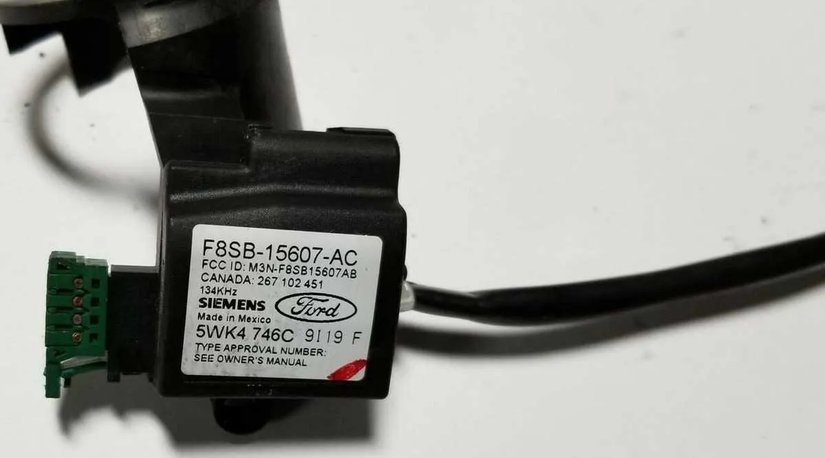
If you’re looking to locate the component of the vehicle’s ignition security system embedded within the dashboard interface, begin by inspecting the central control unit beneath the dashboard assembly. It is crucial to understand the connection between the key reader and the transponder chip within the ignition switch assembly.
The primary function of the unit is to authenticate the key by establishing a communication with the electronic security module when the ignition is turned. You’ll typically find it secured within the column assembly, where it interacts with the central computer to enable engine start-up.
To gain a more comprehensive understanding of its operation, consult the detailed electrical layout of the ignition system. Check for any malfunctions or potential wiring issues that may prevent the security module from correctly recognizing the encoded chip signal from the key. Identifying these connections ensures you can troubleshoot any failure in the starting sequence effectively.
Component Layout for Vehicle Anti-Theft System in Driver’s Console

To troubleshoot or replace the components of the anti-theft system located in the driver’s console, start by inspecting the keyless entry module and transponder. These elements are integral to the system’s operation. Below are the steps to accurately assess and locate each component:
- First, remove the airbag and cover panel to expose the control unit within the dashboard assembly.
- Identify the small antenna ring that surrounds the ignition assembly. It plays a crucial role in communication with the embedded chip in the key.
- Check the wiring harness for any signs of damage or wear. The connections should be secure and free from corrosion.
- Inspect the module connected to the central wiring for proper signal reception and transmission.
- If the system fails to respond, test the transponder in the ignition switch for continuity and proper alignment.
Regular maintenance of these components is essential to ensure the reliability of the system. Ensure no interference with the antenna ring, as it could prevent the correct signal processing from the chip inside the key.
Understanding the PATS System Components in the 2002 Ford Mustang Steering Wheel

When dealing with the Passive Anti-Theft System (PATS) in the vehicle’s ignition system, it’s essential to know the key components located within the driver’s hub assembly. The primary parts involved include the transceiver module and the key’s RFID chip. The transceiver reads the chip’s signal to validate the key, allowing the engine to start. This system is embedded within the central area of the vehicle’s control system, ensuring secure ignition access.
The transceiver, typically positioned near the ignition area, detects signals transmitted from the encoded key. It communicates with the vehicle’s onboard computer to verify the authenticity of the signal. Without a correct match, the ignition system remains disabled to prevent unauthorized operation.
Make sure to check for any issues with the transceiver connections, especially if you experience intermittent starting problems. Worn-out or damaged key chips can also affect the system’s ability to authenticate, so maintaining a good condition of your key is vital. It’s recommended to replace any damaged transceiver modules or faulty key components promptly to avoid future malfunctions.
Troubleshooting Immobilizer System Wiring Issues in the Column
If the vehicle is not starting or there are issues with the ignition, the problem may lie within the wiring associated with the anti-theft immobilizer. Begin by inspecting the connection points for any signs of corrosion, loose pins, or damaged cables in the column area. This is crucial, as even minor disruptions in the wire harness can lead to communication failures between the transponder and the system, preventing the car from starting.
Next, verify that the electrical contacts around the ignition switch are intact and free from dirt or moisture. Damaged contacts can interfere with the signal transmission required for the immobilizer to activate. Use a multimeter to check the continuity across key wiring connections to ensure they’re fully operational.
Another critical step is checking for shorts or breaks in the wiring beneath the cover. The cable leading to the receiver module often gets pinched or worn, leading to intermittent faults. Carefully inspect the entire cable length and test with an ohmmeter to confirm proper resistance values.
If the issue persists, consider inspecting the communication module itself. A faulty module can cause inconsistent signals, and in many cases, the entire component will need replacement if it’s beyond repair.
Finally, reset the system once any wiring repairs have been made. This can be done by disconnecting the battery and allowing the system to reset for a few minutes before reconnecting. If the issue persists, further diagnostic tools or professional help may be necessary.
Steps for Replacing a Faulty Sensor in the Vehicle’s Control Mechanism

1. Disconnect the Battery
Before starting the repair, always disconnect the vehicle’s battery. This prevents accidental airbag deployment or electrical shorts during the process.
2. Remove the Airbag Module
Locate the retaining bolts on the airbag assembly and remove them using a wrench. Carefully lift the module away, ensuring that the wiring connections are not damaged. Disconnect the electrical connectors with a flat tool or small screwdriver to avoid pinching the cables.
3. Unscrew the Central Nut
Using a ratchet wrench, remove the large central nut securing the component in place. Ensure the nut is removed completely before attempting to detach the device from the column.
4. Detach the Assembly
With the central nut removed, carefully pull the part away from the column. Be cautious not to strain the wiring. If resistance is felt, double-check for any remaining screws or connections.
5. Locate the Faulty Sensor
Identify the malfunctioning sensor, which is typically located on the back of the component. The faulty unit will likely show signs of wear, corrosion, or improper connections.
6. Replace the Sensor
Gently disconnect the faulty sensor by unscrewing it or releasing any clips holding it in place. Install the new sensor by reversing the removal process. Ensure that the connections are tight and secure.
7. Reassemble the Components
Reattach the assembly by reversing the disassembly steps. Secure the component with the central nut, ensuring it’s tightly fixed to the column. Reconnect the airbag module and tighten the bolts.
8. Reconnect the Battery
Reconnect the vehicle’s battery, then turn the ignition to test the new sensor. Verify that the system is functioning properly and that no warning lights remain illuminated.