When designing a fluid transfer mechanism for high-efficiency systems, focus on the essential elements that ensure smooth operation. These systems rely on mechanical devices that transfer liquids under pressure to various parts of the machinery. Identifying key components, such as the intake and discharge valves, is critical for optimal performance.
For better reliability, prioritize using durable seals and filters to prevent contaminants from entering the system. Regular maintenance and checks for wear and tear on the moving parts will significantly reduce the risk of system failure and increase longevity.
Ensure proper alignment and calibration of the internal gears, which play a crucial role in fluid movement. Misalignment can lead to inefficiencies and even damage to the entire system over time.
Proper monitoring of fluid levels and pressure is essential for preventing malfunction. Invest in sensors and pressure gauges to detect irregularities early on, allowing for immediate corrective action. Efficiency is maximized when these steps are followed consistently.
Essential Components of a Lubrication System

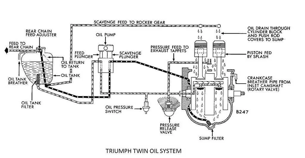
For a fully functional lubrication system, ensure that all critical parts are correctly arranged. A clear understanding of the flow mechanism is necessary for efficient performance and longevity of machinery.
- Reservoir: A tank that stores the fluid, ensuring an adequate supply to the entire system. It should be placed in an accessible location for easy refilling and maintenance.
- Intake: This part draws the fluid from the storage tank into the system. Ensure that the intake pipe is not obstructed, as this can cause poor fluid circulation.
- Pressurizing Element: A mechanical or electric device responsible for forcing the fluid through the system at the correct pressure. Regular inspection for wear and tear is essential.
- Distribution Pathways: Pipes and tubes that carry the fluid to the required points. Ensure they are properly sealed and insulated to prevent leaks or contamination.
- Filters: Filters are crucial for removing contaminants from the fluid before it reaches sensitive components. These should be checked and replaced periodically to maintain system cleanliness.
- Delivery Point: The end destination where the fluid is dispensed onto moving parts. Ensure proper alignment and clearance to guarantee smooth distribution.
Regular maintenance is key to preventing system failures. Monitor the pressure and flow regularly and replace any parts that show signs of wear.
Understanding the Components of a Pump System

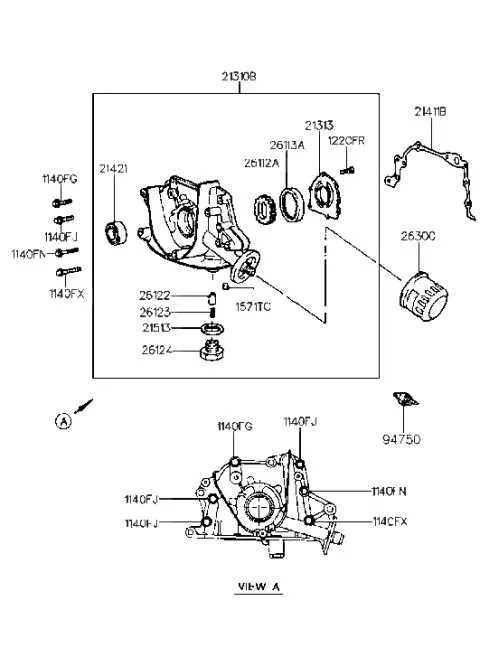
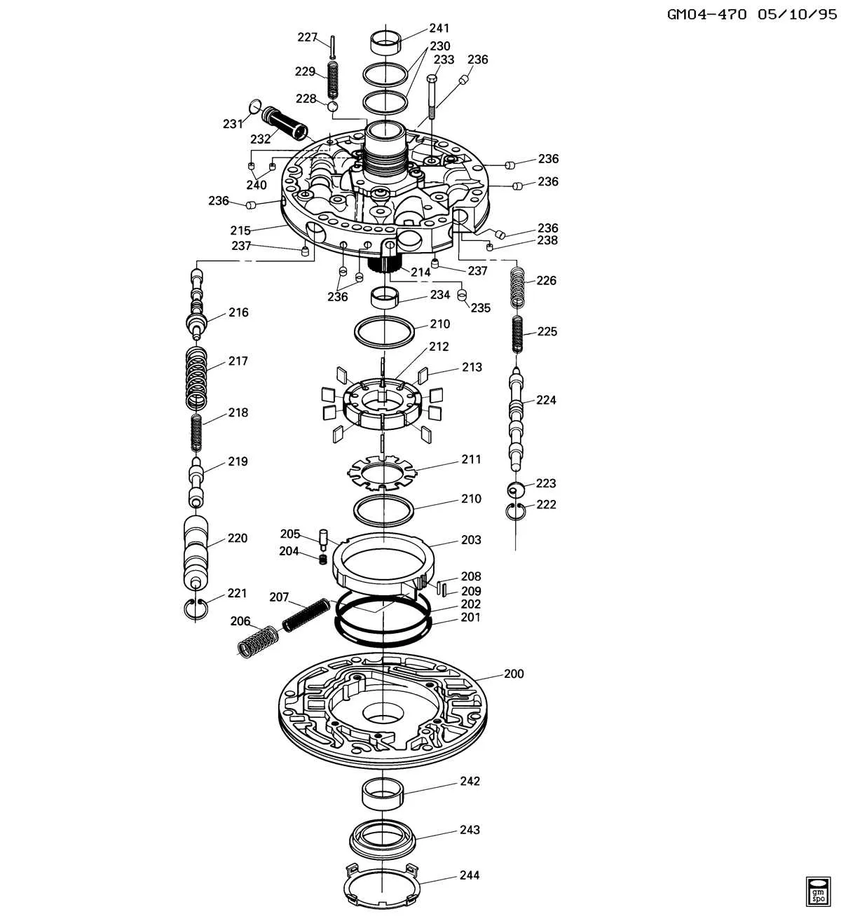
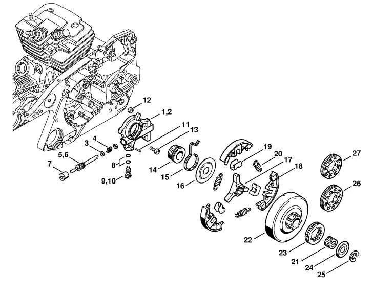
Start by familiarizing yourself with the primary elements of a lubrication delivery system. Focus on the key parts such as the intake, rotor, and discharge valve, each playing a crucial role in fluid movement. The intake component draws in the substance, while the rotor initiates the flow. The discharge valve ensures the fluid is released in a controlled manner, maintaining steady circulation.
Pay attention to the housing, as it forms the core structure around the internal components, providing stability and reducing wear. Also, consider the seals that prevent leakage, ensuring efficiency and preventing contaminants from entering the system. The bearings play a vital role in supporting moving parts, minimizing friction and wear.
The drive mechanism, typically connected to an engine or motor, powers the system, allowing it to function at the required speed. In some setups, an additional bypass valve is included to regulate pressure and prevent overloading.
Understanding each of these parts allows for better troubleshooting, maintenance, and optimization of the entire mechanism. Ensure regular inspection of each component to maintain optimal performance and longevity.
How to Interpret the Flow Direction in a Pump System
Start by identifying the inlet and outlet connections. The flow direction is indicated by arrows, typically placed near the flow paths. These arrows are crucial for understanding how fluid travels through the system.
Next, check the orientation of the internal components such as the gears or rotors. In systems with multiple stages, each stage will usually have its own directional flow indicated by separate arrows.
If you see a single arrow pointing towards the central part, it means fluid is being drawn into the core. An arrow pointing outward indicates discharge from the center. Understanding the position of these arrows in relation to the component parts helps confirm the intended fluid movement.
For systems with bypass valves or check valves, look for additional symbols that clarify the control mechanism for flow redirection. These valves might change the flow during operation, and their function will be represented by smaller directional indicators.
Lastly, always consider the system’s intended function. High-pressure zones are typically associated with fluid leaving the system, while low-pressure or intake areas are linked to the fluid entering. This provides additional context to the directional markings.
Common Issues Identified in Pump Systems and Their Solutions

Ensure correct alignment of all components. Misalignment often leads to irregular flow or pressure spikes, which can cause system failure. Regularly check the bearings and housing to verify proper positioning.
Inspect for contamination within the fluid circuit. Foreign particles can block pathways, leading to overheating or reduced efficiency. Implement filtration systems to capture impurities and prevent wear on critical parts.
Monitor seals and gaskets for wear or damage. Leaks from improperly sealed parts result in pressure loss or contamination. Replace seals when necessary and verify installation accuracy to maintain integrity.
Verify system pressure settings. Incorrect pressure can strain internal components, leading to excessive wear. Use calibrated pressure gauges to ensure pressure remains within operational limits, adjusting valves as needed.
Check for cavitation, which occurs when pressure drops too low, causing air bubbles to form. This can cause significant damage. Adjust the inlet conditions or increase suction to prevent this issue.
Maintain consistent lubrication levels. Insufficient lubrication results in excessive friction and heat buildup, leading to premature component failure. Regularly check fluid levels and replenish as required to ensure smooth operation.
Examine the rotational speed of the mechanism. Operating outside the recommended speed range can cause instability and wear. Use tachometers to monitor and adjust speed accordingly.
Ensure correct mounting and secure fasteners. Loose bolts or improper mounting can result in vibration, which further damages parts. Tighten connections and check for any loose components regularly.