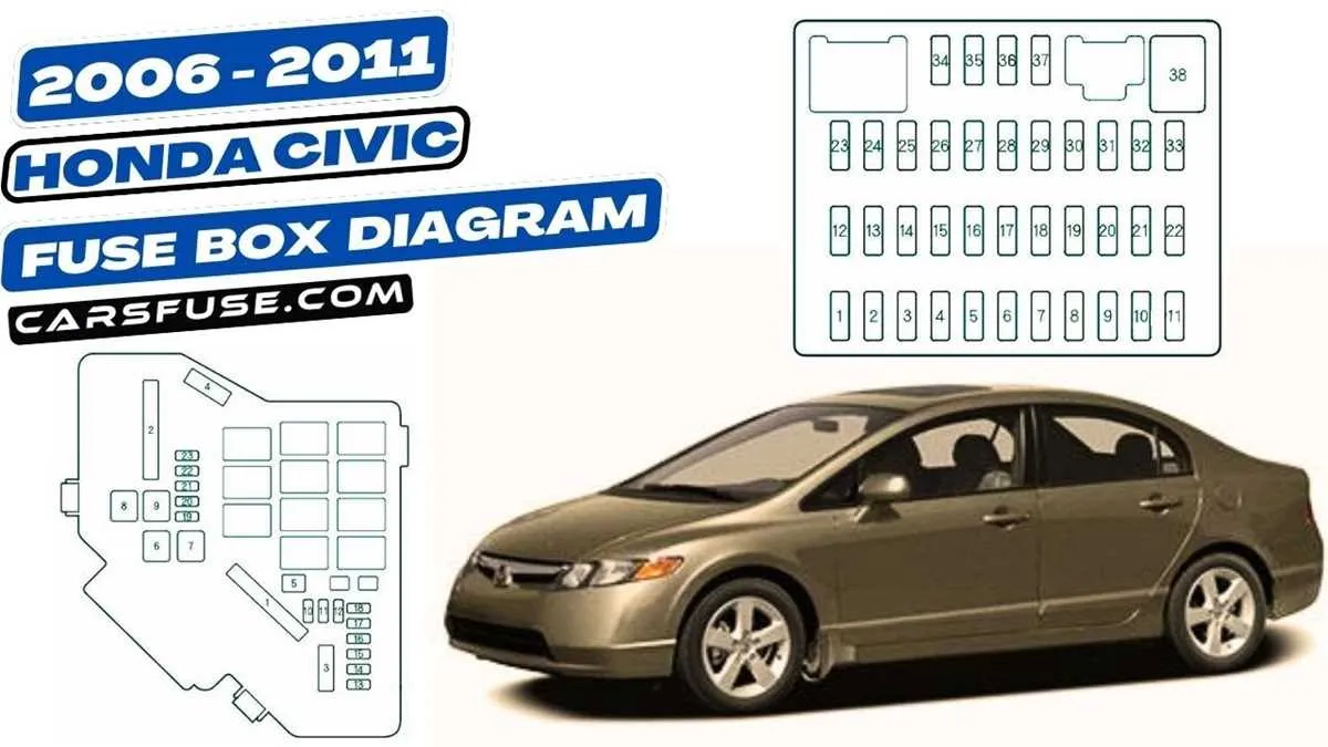
Start by inspecting the compartment beneath the dashboard on the driver’s side. To access the relay configuration and protectors, pull the small panel outward. A printed map on the reverse side will display slot numbers and corresponding components such as turn indicators, power windows, and the radio unit.
For elements related to engine management and air conditioning, check the auxiliary unit located under the hood, near the battery. Lift the black plastic cover by pressing the side clips. Inside, a schematic outlines positions for high-amperage circuits, including the cooling fan, ignition coil, and ABS control.
Common replacement slots: 12 (cigarette lighter/accessory), 9 (interior lights), 15 (fuel pump), and 7 (airbags). Use the chart under the lid or consult the owner’s manual for precise details. Always match amperage ratings to avoid electrical damage.
If troubleshooting persistent electrical faults, verify connections for corrosion or looseness, especially in moisture-prone areas. A multimeter can help confirm continuity across suspected relays and mini protectors.
2008 Honda Civic Fuse Box Diagram

Locate the under-hood panel near the battery on the driver’s side. Release the latches to open the black plastic cover and check the inside for a labeled chart. Each square or rectangular slot corresponds to a circuit; for example, slot 15A handles the fuel pump, while 20A may control the cooling fan motor.
For interior circuits, find the secondary compartment beneath the dashboard, slightly left of the steering column. Pull the tab to access the terminal layout. Use the legend printed on the reverse side of the lid to identify modules like power windows (20A), radio (15A), or air conditioning (10A).
When replacing components, always match the amperage rating. Use needle-nose pliers or the provided puller to extract blown units. A transparent plastic housing with a visible broken wire confirms failure.
Tip: Keep spare low-profile ATM-style elements in the glove compartment. Avoid substitutions above the designated rating to prevent electrical damage or fire.
How to Locate the Interior and Under-Hood Fuse Boxes in a 2008 Honda Civic
Start by opening the driver’s side door and crouching near the footwell. On the lower left of the dashboard, just above the pedals and next to the kick panel, you’ll find the in-cabin relay housing. Remove the small rectangular cover by pulling its edge outward; the label on the inside indicates circuit assignments.
For the engine bay unit, pop the hood and stand facing the vehicle. Look toward the rear right corner near the battery. The black plastic enclosure with a snap-on lid is mounted on the fender apron. Press the side tabs to lift the cover. Inside, a schematic identifies each terminal’s function, including key systems like the cooling fan, ABS, and ignition.
Fuse Functions and Ratings for the 2008 Honda Civic: Complete Layout by Circuit
Check the driver’s side panel for the interior circuit array. Here are the key assignments and amperage values:
- Power Window Relay (No. 23): 20A – Controls all electric window motors.
- ABS Modulator (No. 7): 7.5A – Ensures anti-lock functionality is maintained.
- Accessory Socket (No. 28): 15A – Powers front console outlet.
- Left Headlamp Low Beam (No. 14): 10A – Regulates driver-side low beam light.
- Right Headlamp Low Beam (No. 15): 10A – Regulates passenger-side low beam light.
- Gauge Assembly/Backlight (No. 13): 10A – Controls instrument cluster lighting.
- Rear Defroster Relay (No. 12): 30A – Powers heating grid in rear glass.
Under the hood, check the engine compartment relay center. Key entries include:
- Cooling Fan Motor (No. 1): 20A – Regulates radiator fan speed.
- Ignition Coil/ECM (No. 15): 15A – Controls electronic engine management system.
- Starter Signal (No. 18): 7.5A – Transmits signal to engage starter motor.
- Horn and Stop Light (No. 20): 15A – Combined protection for horn and brake indicators.
- AC Compressor Clutch (No. 21): 7.5A – Powers air conditioning engagement mechanism.
- Main Fan Relay (No. 2): 30A – Controls activation of the primary cooling fan.
Always match the replacement amperage precisely. Use only blade-type mini modules rated to the manufacturer’s specification to avoid overload or component failure.
Steps to Replace a Blown Fuse Safely
Begin by disconnecting the vehicle’s battery to prevent electrical shocks. Locate the power distribution panel beneath the dashboard or in the engine compartment. Use the panel cover’s label to identify the faulty protective element associated with the malfunctioning system.
Remove the damaged component carefully using a fuse puller or needle-nose pliers, avoiding damage to adjacent units. Inspect the removed piece for a broken filament or discoloration as confirmation of failure.
Select a replacement with the exact amperage rating indicated on the original to maintain system integrity and prevent electrical hazards. Insert the new protective device firmly into the designated slot until it is fully seated.
Reconnect the battery and test the affected electrical system to ensure proper operation. If the issue persists or the replacement component blows again quickly, investigate underlying wiring problems or seek professional diagnostics.