If you’re planning to maintain or repair a watercraft’s motorized propulsion, understanding the core components is crucial. A typical setup involves several essential parts: the power unit, the cooling system, the drive shaft, and the propeller. Each element plays a specific role in ensuring efficient operation on water.
The power unit, often referred to as the heart of the system, requires regular inspection for wear and tear. Key components such as the fuel system, ignition, and electrical connections need proper maintenance to ensure reliable starts and smooth operation. The cooling system prevents overheating, with the pump and thermostat requiring particular attention. Any signs of corrosion should not be overlooked, as they can lead to costly repairs if not addressed early.
The drive shaft links the power source to the propeller, transferring rotational energy. Over time, the shaft and its associated bearings can suffer from wear, causing reduced efficiency. Regular lubrication is essential to minimize friction and prolong the lifespan of these parts. Similarly, the propeller must be checked for any damage that could affect thrust. A bent or chipped blade will reduce speed and fuel efficiency.
Each of these components should be understood in depth, as any malfunction in one area can impact the performance of the entire system. Regular checks and prompt repairs will not only enhance the boat’s lifespan but also ensure safe and optimal performance on the water.
Understanding the Components of a Marine Motor

For optimal performance, familiarize yourself with the key parts of a marine propulsion system. These elements are crucial for the efficiency, longevity, and safety of the unit.
- Powerhead: This is the central part, housing the internal combustion mechanism and associated systems such as fuel and ignition components.
- Lower Unit: Includes the gearcase, which connects the propeller shaft to the engine and houses the gears that control forward, neutral, and reverse operation.
- Propeller: The rotating blades responsible for generating thrust, converting mechanical power into forward movement.
- Cooling System: Ensures that the motor does not overheat. It typically includes a water pump that circulates water around the unit to maintain optimal operating temperatures.
- Steering Mechanism: This system allows the operator to control the direction of the vessel, connecting the unit to the helm through either a mechanical or hydraulic linkage.
Regular inspection of these parts helps maintain smooth operation and avoids costly repairs. Pay attention to wear and tear on the propeller and lower unit, as they are exposed to harsh marine conditions.
- Fuel System: Includes the tank, filter, and fuel pump. Ensure proper fuel flow and check for blockages or leaks.
- Electrical System: The alternator and battery provide power for ignition and auxiliary systems. Regular checks can prevent unexpected shutdowns.
- Throttle and Shift Mechanism: This controls the speed and gear selection. Ensure cables or hydraulic lines are free of damage and properly adjusted.
Proper maintenance and understanding of these components will improve the lifespan and performance of your vessel’s power system.
Understanding the Key Components of an Outboard Engine Diagram

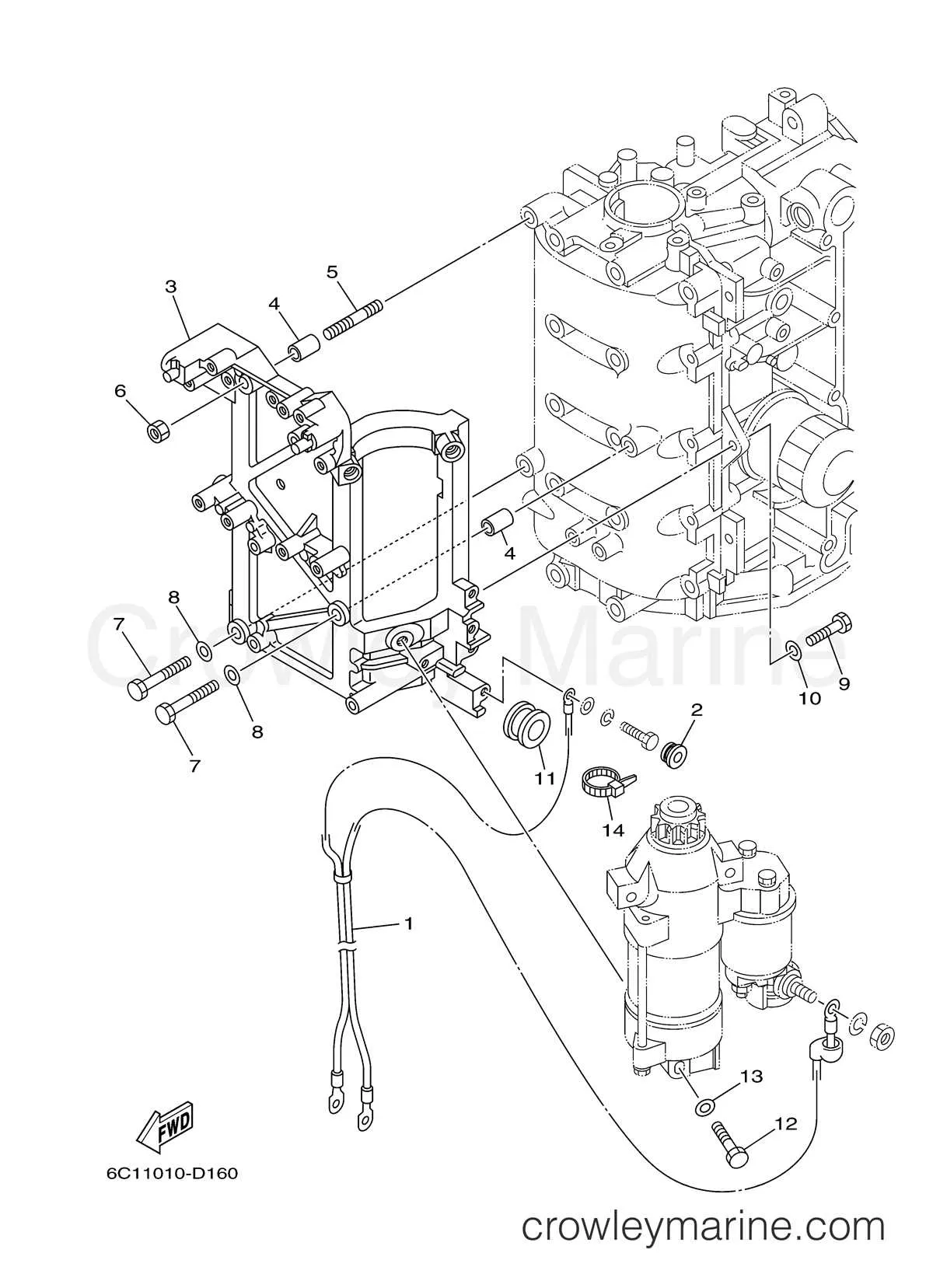
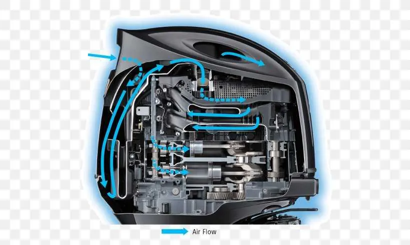
Focus on the powerhead, as it is the core of the motor, housing the combustion chamber and generating the necessary force for propulsion. Pay attention to the crankshaft, which converts the reciprocating motion of the pistons into rotational movement. This component is essential for transferring power to the rest of the system.
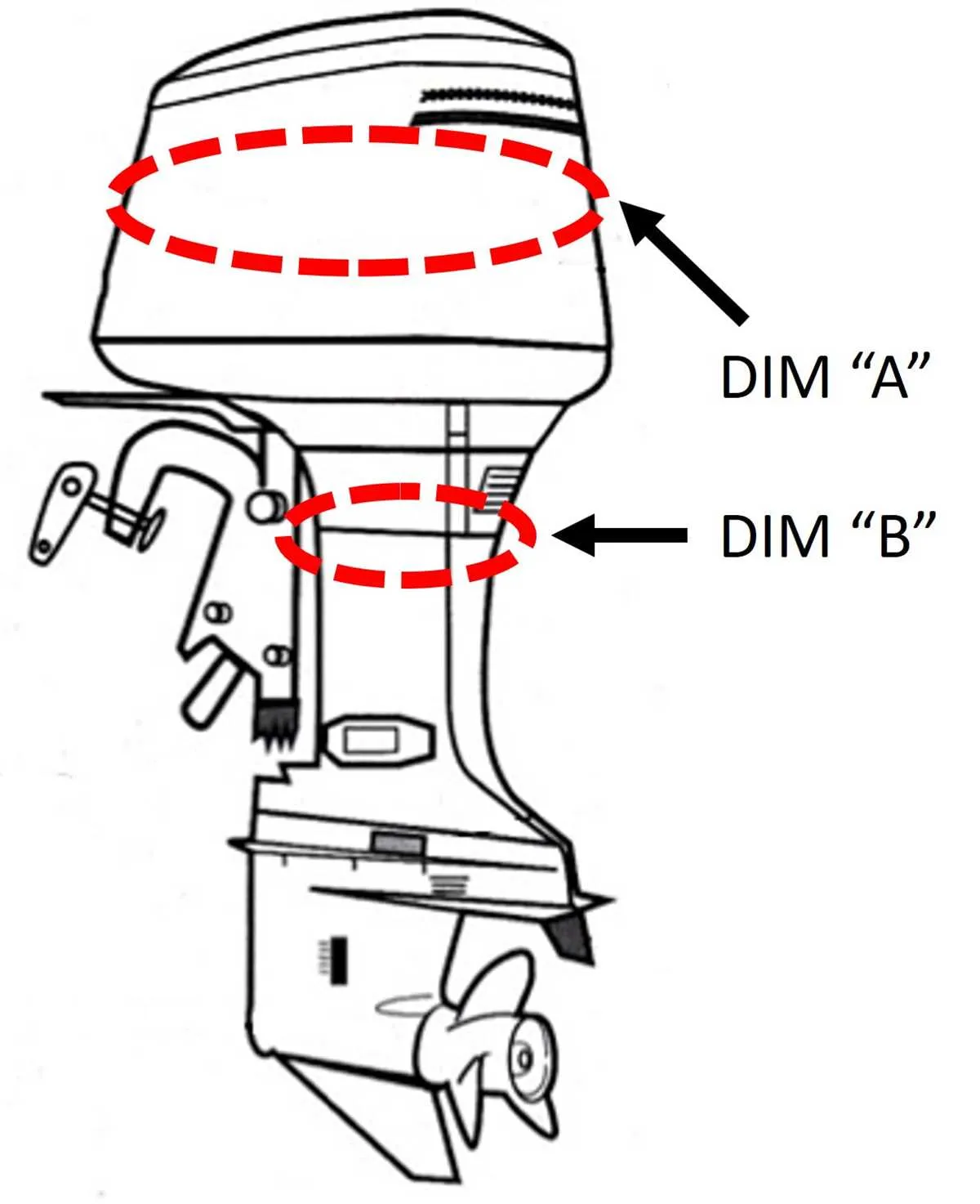
The lower unit, also known as the gearbox, houses crucial parts like the propeller shaft and the gears that control forward, neutral, and reverse operations. Examine the positioning of the propeller, as it is directly linked to the thrust and the direction of the vessel.
Don’t overlook the fuel system, which includes the carburetor or fuel injector, as well as the fuel pump, which ensures a continuous supply of fuel to the combustion chamber. Proper attention to this area is key for optimizing performance and fuel efficiency.
The cooling system is another crucial aspect. Look at the water pump and the cooling passages that prevent the motor from overheating. Ensure that the water intake is unobstructed for effective operation.
Lastly, examine the electrical components, such as the starter motor and the ignition system, which regulate starting, timing, and overall electrical functions of the vessel’s motor. Keeping these parts in top condition will ensure smooth operation and minimize downtime.
How to Read and Interpret an Outboard Engine Wiring Diagram
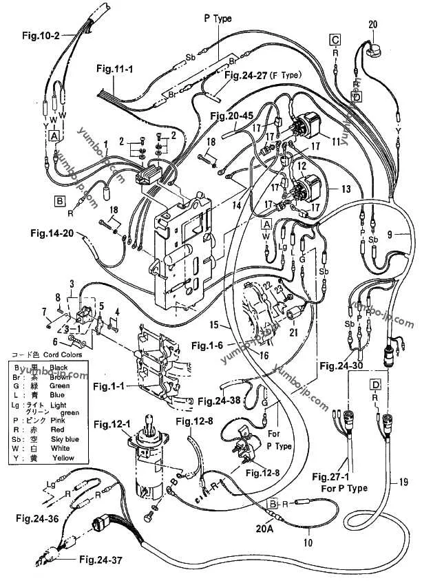
Start by identifying the power source: locate the battery symbol, usually marked with a plus (+) and minus (–) sign. Trace the positive lead to the ignition switch and fuse block–these are critical for circuit protection and activation.
Follow color codes consistently: red wires typically carry power, black or yellow/black are common grounds. Use the key or legend to decode any color-specific functions. Never assume color meanings without reference.
Track individual circuits: for example, to understand the starter system, locate the solenoid symbol, then trace the circuit back through the ignition switch and forward to the starter motor. Confirm all connections, including any relay or neutral safety switch inline.
Identify connectors and terminal labels: look for symbols such as rectangles with letter/number codes (e.g., “C1”, “J2”). Cross-reference these with harness maps or service manuals to verify their exact physical location.
Pay attention to ground paths: poor grounding is a common cause of malfunction. Ensure every negative wire returns to the chassis or battery terminal with a clear, uninterrupted path.
Use a multimeter to validate paths: continuity testing helps confirm the accuracy of visual inspection. Disconnect power before probing circuits to avoid shorting sensitive components.
Tip: highlight critical paths–ignition, charging, starting–with different colors during analysis to simplify troubleshooting and ensure correct reassembly after maintenance.
Common Issues Identified in Outboard Engine Diagrams and Their Fixes

Replace corroded electrical connections immediately. Saltwater exposure accelerates oxidation at terminal points, often visible as greenish residue or brittle wiring near the ignition coil or stator. Use marine-grade heat shrink connectors and dielectric grease for long-term protection.
Inspect cooling passages for salt or debris buildup if overheating is observed. A clogged water jacket or restricted impeller housing commonly leads to reduced flow. Flush with pressurized freshwater and, if needed, disassemble the pump to clear obstructions.
Misaligned throttle linkage often results in rough idling or delayed response. Ensure that the control cables move smoothly and the synchronizing marks between the throttle cam and timing advance are precisely aligned. Adjust using a feeler gauge and verify with a timing light.
Fuel delivery problems frequently stem from degraded lines or a compromised primer bulb. Check for soft spots, cracks, or fuel seepage. Replace all ethanol-damaged rubber components with alcohol-resistant variants and secure connections using stainless steel clamps.
Examine reed valves for chipping or warping when low compression is present in one cylinder. Remove the intake manifold and test valve tension with a feeler blade. Replace damaged petals with OEM-specified carbon fiber or stainless steel parts for proper sealing.
Unstable charging output often traces back to a failing rectifier-regulator. Measure voltage across battery terminals at 3,000 RPM; readings below 13.5V or above 15V indicate malfunction. Swap with a compatible marine-grade unit and verify output under load.