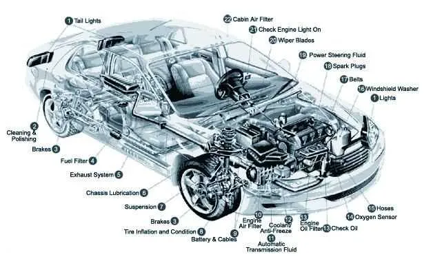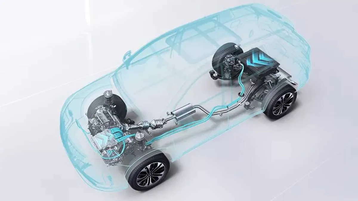
Start by inspecting the frame rails–these longitudinal supports run along both sides and form the backbone of the entire lower build. Look for corrosion, cracks, or previous repairs, especially near the suspension mounting points.
Check the condition of the exhaust line. From the manifold to the tailpipe, follow each segment and joint. Pay close attention to the catalytic converter and oxygen sensors. Surface rust is normal; flaking metal is not.
Evaluate the suspension layout. Front and rear setups may differ–MacPherson struts in front, multilink or torsion beam in back. Examine control arms, bushings, and anti-roll bars for wear or damage.
Observe the drivetrain path from the transmission housing to the wheels. In all-wheel-drive models, the prop shaft and rear differential must be checked for fluid leaks and intact boots on CV joints.
Don’t overlook brake lines and fuel conduits. These often run parallel to each other along the chassis. Look for secure mounting clips and any signs of rubbing or leakage, especially near wheel wells.
Key Components Visible from Below the Vehicle
Begin inspection by locating the exhaust system running along the center. Identify the catalytic converter, usually positioned between the engine and the muffler, and check for heat shield integrity and rust.
Next, focus on the suspension layout. In the front section, observe the control arms, sway bar, and coil springs. Ensure bushings are not cracked and that joints show no signs of oil leakage, which may indicate worn seals.
Move to the drivetrain. For rear-wheel configurations, identify the driveshaft running toward the differential. Check the universal joints for excessive play. On all-wheel systems, note the additional transfer case and rear axle connections.
Brake lines and fuel lines typically run parallel to the frame rails. Inspect for corrosion, especially near mounting brackets. Rubber hoses near the tank or engine should be pliable and free from cracks.
The floor pan and crossmembers should be free of dents and structural damage. Surface rust is common, but flaking metal or holes require immediate attention. Reinforcement points and jack mounts must remain solid.
Identifying Key Components in a Car Undercarriage Diagram

Start by locating the suspension system. Focus on control arms, sway bars, and coil springs–these parts maintain handling and absorb road impact. Control arms usually appear as A-shaped links connecting the wheel hub to the frame.
Next, examine the exhaust route. Identify the catalytic converter, muffler, and tailpipe. The converter sits near the engine end, often shielded by heat guards. The muffler is typically a larger chamber closer to the rear axle.
Inspect the drivetrain assembly. For front-wheel drive, look for CV axles extending from the transaxle to the front wheels. On rear-wheel configurations, note the driveshaft running longitudinally from transmission to differential.
Check for braking elements such as brake lines, calipers, and rotors. Brake lines are thin metal tubes following the frame; calipers clamp around the discs behind each wheel hub.
Finally, locate the fuel system. The fuel tank is usually mounted between the rear wheels with protective shielding. Look for fuel lines running along the frame toward the engine bay.
How to Read Symbols and Labels on Underside Schematics
Start by locating the legend or key, usually positioned in a corner of the technical sheet. It explains abbreviations such as:
- HMB – Heat Management Barrier
- LCB – Lower Control Bracket
- RRX – Rear Axle Crossmember
- TPU – Transmission Protection Unit
Electrical lines are often marked with dashed or dotted paths. A dashed line with a triangle may indicate a ground connection. A solid arrow shows current flow direction.
Fasteners are typically labeled with bolt class and torque spec. For example:
- M10x1.25 – 45Nm = Metric bolt, 10mm diameter, 1.25mm pitch, torque 45 newton-meters
Fluid lines are color-coded in many schematics:
- Blue – coolant
- Red – transmission fluid
- Green – brake fluid
Crosshatch patterns often indicate shielding or composite materials. Double-hatched areas may refer to sound insulation zones. Components marked with circled numbers usually correspond to parts lists on adjacent pages.
When identifying mounting points, look for labels like:
- MP1 – first structural support
- IS2 – second isolation mount
Always cross-reference component tags (e.g., SEN12) with system tables to confirm sensor types and their location in the layout.
Using Undercarriage Diagrams for DIY Maintenance and Inspection
Start by identifying key components such as the exhaust system, suspension, brake lines, and drivetrain layout. Accurate schematics help locate wear points and leaks without guesswork.
Check for corrosion or damage on metal parts by referencing the layout to pinpoint vulnerable sections, especially near joints and mounting brackets. Early detection prevents costly repairs.
Use the illustration to track fluid lines and hoses for cracks or leaks. Follow the routing carefully to ensure no sections are missed during visual inspection.
Inspect fasteners and bolts according to their positions shown in the layout to confirm proper torque and tightness, crucial for safety and performance.
Refer to the schematic to plan underbody cleaning and rust-proofing, targeting exposed areas prone to dirt accumulation and moisture retention.
Leverage the structural overview to align lifting points correctly before raising the vehicle, preventing damage to frame rails and suspension arms.
For brake maintenance, the detailed layout enables quick identification of calipers, rotors, and brake line paths, streamlining replacement or repair tasks.
When replacing parts like control arms or sway bars, the visual reference aids in recognizing exact mounting spots and bolt patterns, reducing installation errors.