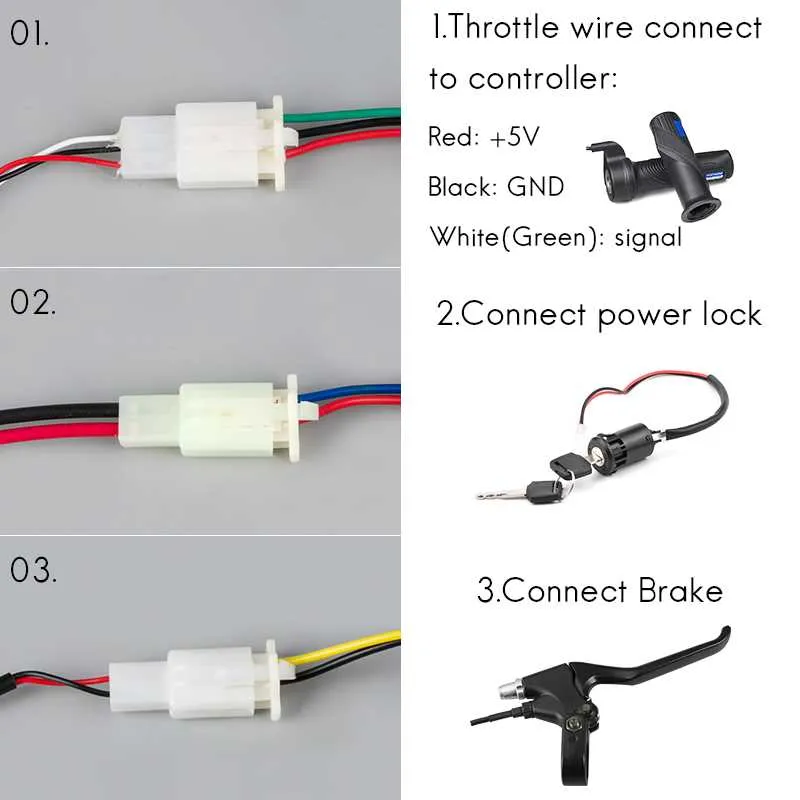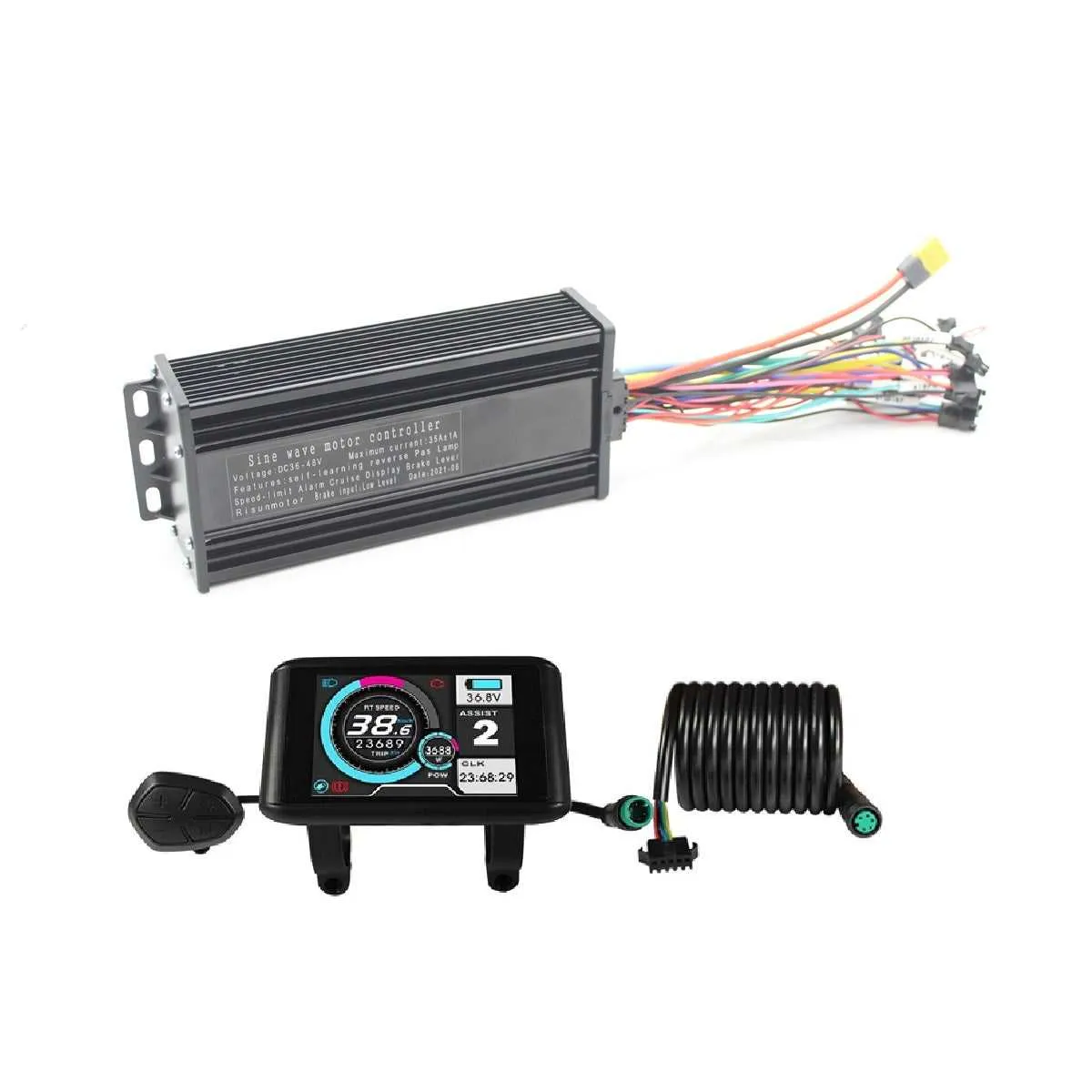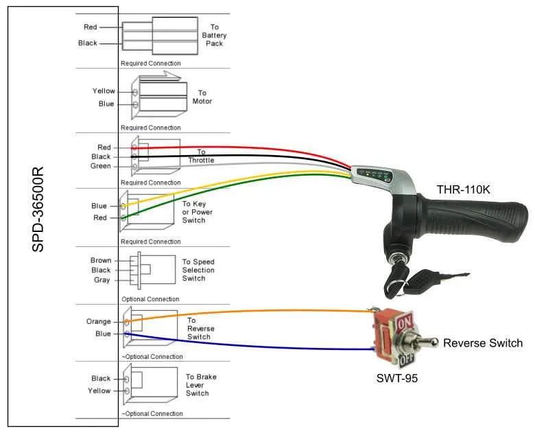
If you’re looking to configure a 3-level gear selection for your electric bicycle system, start by focusing on the precise connections needed to control the motor’s performance. Each wire serves a distinct function, whether it’s controlling the power flow or switching between modes. Ensure that your connections are secure to avoid power interruptions during operation.
First, identify the key components: The throttle, the mode selector, and the control unit. These parts communicate with each other to provide the necessary power adjustments. You’ll need to establish proper connections between the mode selector and the control system to ensure smooth transitions between the three levels.
Pay attention to voltage ratings: Different systems may operate at varying voltages, so be sure to match the wiring and components accordingly. Incorrect voltage levels can lead to malfunction or even damage. Additionally, use high-quality connectors to ensure long-term reliability.
When connecting the wires, make sure to follow a logical flow: the power wire should be routed to the controller first, and then split to the selector. A clean setup minimizes the chances of interference or signal loss. Avoid over-complicating the process with unnecessary components, as this can increase the risk of error.
Finally, double-check all connections before testing the system. A well-executed setup will ensure that you can easily toggle between low, medium, and high power levels, optimizing your bike’s performance based on your needs.
Connecting the 3-Position Gear Selector to the Motor System
To properly integrate the three-level gear selector with your motor control unit, first locate the connector on the main control board where the gear switch wiring is to be attached. This will typically be a 3-pin connector designed for low voltage input from the selector. Make sure the wiring is firmly connected, with each pin corresponding to the distinct positions (low, medium, and high) of the selector.
Ensure that the ground wire is securely connected to the control unit’s ground terminal. The other two wires should correspond to the positive outputs for the two remaining gear settings. Proper insulation and protection for these wires are important to prevent short circuits. Test the connection by switching between gear positions while monitoring the system’s response for any inconsistencies or failures in signal detection.
If you notice that the system is not responding as expected, double-check the pinout configuration against your motor controller’s manual. In some cases, the signal input might require specific voltage levels, so confirm that the power supply is adequate for the signal processing unit.
Connecting the 3-Level Adjustment Mechanism

Start by identifying the terminals for each level of control on the device. You’ll typically find three positions, each corresponding to a specific function: low, medium, and high. Use color-coded wires for clear identification of each setting. Secure the connections to the appropriate terminals on the module, ensuring that each wire is tightly connected to avoid issues during operation.
Low Setting: Connect the wire for the lowest performance to the first terminal. This will limit the output power to provide maximum efficiency at lower speeds. Double-check that the connection is solid to avoid unexpected behavior.
Medium Setting: For the middle range, link the wire to the second terminal. This will allow for a balanced level of output, offering a good compromise between range and speed.
High Setting: The last wire goes to the third terminal, which activates the highest performance. Ensure this connection is secure, as it controls the device’s highest output levels.
After making the connections, carefully route the wires to avoid any risk of wear or disconnection. Test each setting by cycling through the different positions and checking the responsiveness. If any setting does not function properly, inspect each connection and verify that each wire is correctly placed.
Identifying the Correct Wires for Speed Control Functionality
First, locate the signal wire, which is typically color-coded for easier identification. This wire is responsible for adjusting the performance level. Usually, it will be a different color from the others and may be marked with a specific number or symbol indicating its role in controlling power modulation.
Second, confirm the ground connection, often found in the form of a black or green wire. This is essential for completing the circuit, and its placement is critical for proper functionality.
Next, identify the input terminal for mode changes. This is the wire that responds to changes when toggled between different operational settings. It can often be found attached to the power selector, and its signal flow needs to be uninterrupted for the correct level to be activated.
Ensure that the wires are connected securely to prevent potential malfunction. Loose or incorrectly connected wires can lead to inaccurate control behavior, which will affect the overall performance.
Lastly, test all connections by running through each available setting. This allows you to verify the response of each functional wire and ensures that the performance adjustments are functioning as expected.
Common Connection Issues and Troubleshooting Tips

Ensure all cables are securely connected before proceeding with any troubleshooting. A loose or damaged connection is often the main cause of issues.
- No power output: Check if the connections to the battery are correct. Incorrect or weak connections can prevent power flow. Clean terminals to remove any corrosion or dirt.
- Unresponsive control inputs: Inspect the connectors for any loose or bent pins. If possible, use a multimeter to check for continuity along each wire.
- Unexpected behavior during operation: Verify that all connections are routed as specified. Incorrectly connected parts may cause erratic functionality. Pay special attention to grounding and voltage input connections.
For more specific troubleshooting:
- Test the components: Use a multimeter to measure voltage at various points along the system. Compare these values against the expected outputs to isolate faulty areas.
- Inspect the fuse: A blown fuse can interrupt operation. Replace any blown fuses and ensure the new fuse matches the required specifications for the setup.
- Check for shorts: Examine all exposed wires for signs of wear or potential shorts. Use insulation tape to secure and protect any exposed sections.
If the system remains unresponsive, check for software errors or firmware updates that could be affecting functionality. Refer to the manufacturer’s manual for specific troubleshooting procedures.