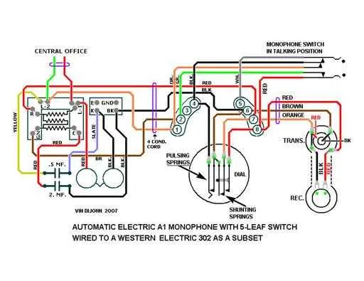
If you are setting up a single-channel communication system, it’s critical to plan your connections carefully. Each element must be correctly placed to ensure seamless signal flow and minimal interference. Start by focusing on the input connections, making sure they are securely linked to the receiving unit. Ensure the power source is correctly rated for the equipment’s requirements to avoid damage or inefficiency.
Next, ensure that the signal transmission paths are isolated from any potential sources of electrical noise. Using high-quality cables and connectors will reduce the risk of signal degradation over distance. Pay attention to grounding points, as improper grounding can lead to unwanted feedback or even equipment failure. Consider using shielded wiring where possible, especially if the installation will be exposed to external electromagnetic fields.
Finally, verify that all terminals and connections are clean and free from corrosion. A simple visual inspection can often identify issues that would otherwise go unnoticed. A reliable test of the system under full load will help confirm the setup is stable and functioning as expected.
Connection Plan for Single-Channel Systems
To ensure proper setup of a single-channel audio system, follow these key steps:
- Begin with selecting the correct wire gauge for the system’s load.
- Ensure all components are powered down before starting the assembly process.
- Use insulated connectors to avoid short circuits and ensure secure connections.
- Start from the source unit and connect the signal path through the amplifier, followed by the speaker or output device.
- Maintain clear cable management to reduce interference and enhance signal clarity.
- If using a circuit board, ensure all components are correctly soldered to avoid weak connections.
For optimal performance:
- Double-check all connections after assembly to avoid signal loss or distortion.
- Ensure the amplifier’s impedance matches the speaker to prevent system overload.
- Position cables away from power lines or any high-interference sources to minimize noise.
Test the system by gradually increasing volume and monitoring for any distortion or inconsistencies in sound quality. Always prioritize safety when handling electrical components.
Understanding the Key Components of a Single-Line Circuit Layout

Begin by identifying the power source, which is the foundation of the entire system. Ensure proper voltage compatibility with the equipment involved. Next, look for the control elements, such as switches and relays, which regulate the flow of electricity to various parts of the system. Proper selection and placement of these components ensure safe operation.
Connectors play a crucial role in maintaining a secure and efficient link between the system’s elements. Pay close attention to their ratings and material quality to prevent electrical faults. For ground safety, the earth connection must be solid, ensuring it handles the current without resistance.
Load components, such as speakers or alarms, are activated once the current flows through them. They must be rated to handle the specific power delivered through the system. Their position within the setup is essential for maximizing functionality while minimizing risk.
Circuit protection devices, like fuses or circuit breakers, are critical for avoiding system overloads and potential damage. These must be rated according to the load requirements and the anticipated electrical fluctuations. Proper placement ensures quick response times in case of faults.
Conductors used in the layout should be selected based on their current-carrying capacity and insulation rating. Ensure the routing of these conductors avoids interference and maintains optimal performance.
Lastly, verify the connection points for consistency and reliability. These must be secure, with no loose or corroded contacts, to maintain long-term operational integrity.
Step-by-Step Guide to Assembling the Electrical Connections for a Single-Channel Audio Device

Start by securing the necessary components: a single-channel speaker, input terminal, and amplifier unit. Ensure each element is compatible with your power source. Use durable, insulated cables to make the connections between the input and amplifier, following the designated polarity markings to avoid short circuits.
Connect the speaker terminals to the output of the amplifier. Double-check for proper alignment of positive and negative connections. For effective sound output, ensure all cables are securely fastened to avoid signal loss.
If using a switch for volume control, integrate it between the amplifier and speaker, ensuring the wiring maintains the integrity of the signal path. A potentiometer will allow precise volume adjustments, so place it in an easily accessible location for user convenience.
When routing the power cables, keep them clear from the signal cables to reduce the chances of electrical interference. Ensure the grounding is done at the appropriate point to prevent hum or noise in the audio output.
After completing the physical assembly, test the connections by powering on the system and verifying the sound quality. If there’s distortion, check the grounding and recheck all connections for accuracy.
Once the system is operational, consider securing the wiring in place with cable ties or clips to prevent movement that could cause wear or damage over time.
Common Troubleshooting Tips for Audio System Connection Problems
Check all cable connections first. Loose or disconnected wires are the most frequent cause of system malfunctions. Ensure all connectors are securely plugged in and that there are no visible signs of damage.
If there’s no sound output, verify the power supply. Sometimes the issue is as simple as a blown fuse or insufficient power reaching the device. Use a multimeter to test the power source and confirm it’s within the specified range.
Inspect for short circuits. This can happen if two wires are touching or improperly insulated. Look for any signs of fraying or wear, especially near connectors or where the cables bend.
Examine the control panel settings. Incorrect configuration can lead to signal failure. Ensure all switches, knobs, or software settings are properly adjusted according to the user manual.
Use a signal tester to check whether the components are receiving the expected input and output signals. This tool helps identify if the problem lies within the input stage, the connections, or the receiving end.
If you experience intermittent sound issues, try grounding the system properly. A poor ground connection can cause noise or unstable behavior. Check all grounding points for corrosion or loose fittings.
For distorted sound, consider checking the impedance compatibility between components. Mismatched impedance can lead to signal distortion or damage over time.
Finally, inspect any potential software or firmware bugs. If the system includes a digital interface, ensure the firmware is up to date and no conflicts are causing erratic performance.