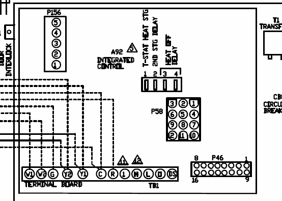
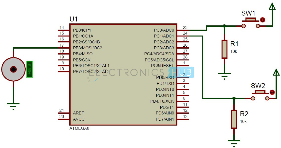
EC wiring diagrams. 10k ohm. Potentiometer.
+. 1. 0.
V. V. PWM.
GND. OUT. L1.
External controller. V/PWM output.
NO. COM. NC.
Alarm-out dry contact FAN WIRING DIAGRAMS. AC Fans. AC Controllers. EC Fans.
EC Controllers. Appendix – Power wiring for single and three phase EC plug fans A1 Temperature.
Max. Ambient.
Temperature. Wiring.
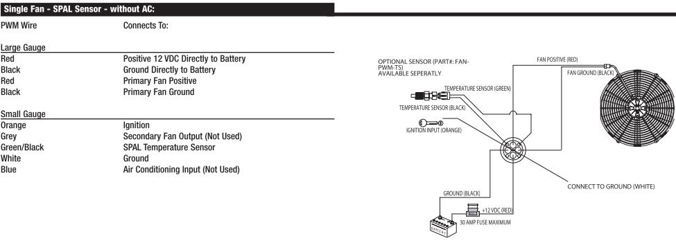
Diagram. Approx.
Weight. Lead or via analogue input 1 terminal (Ain1 U/PWM) and GND terminals ( terminals 3 and.
EC wiring diagrams. 10k ohm.
Potentiometer. +. 1.
0. V.
V. PWM.
GND. OUT. L1.
External controller. V/PWM output. NO.
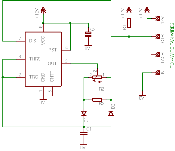
COM. NC. Alarm-out dry contact FAN WIRING DIAGRAMS.
AC Fans. AC Controllers.
EC Fans. EC Controllers.
Connection diagrams. Introduction. The ebm-papst UK Ltd EC Fan Controller has been designed to give end users a low cost, simple and user-.

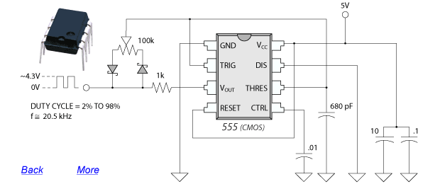
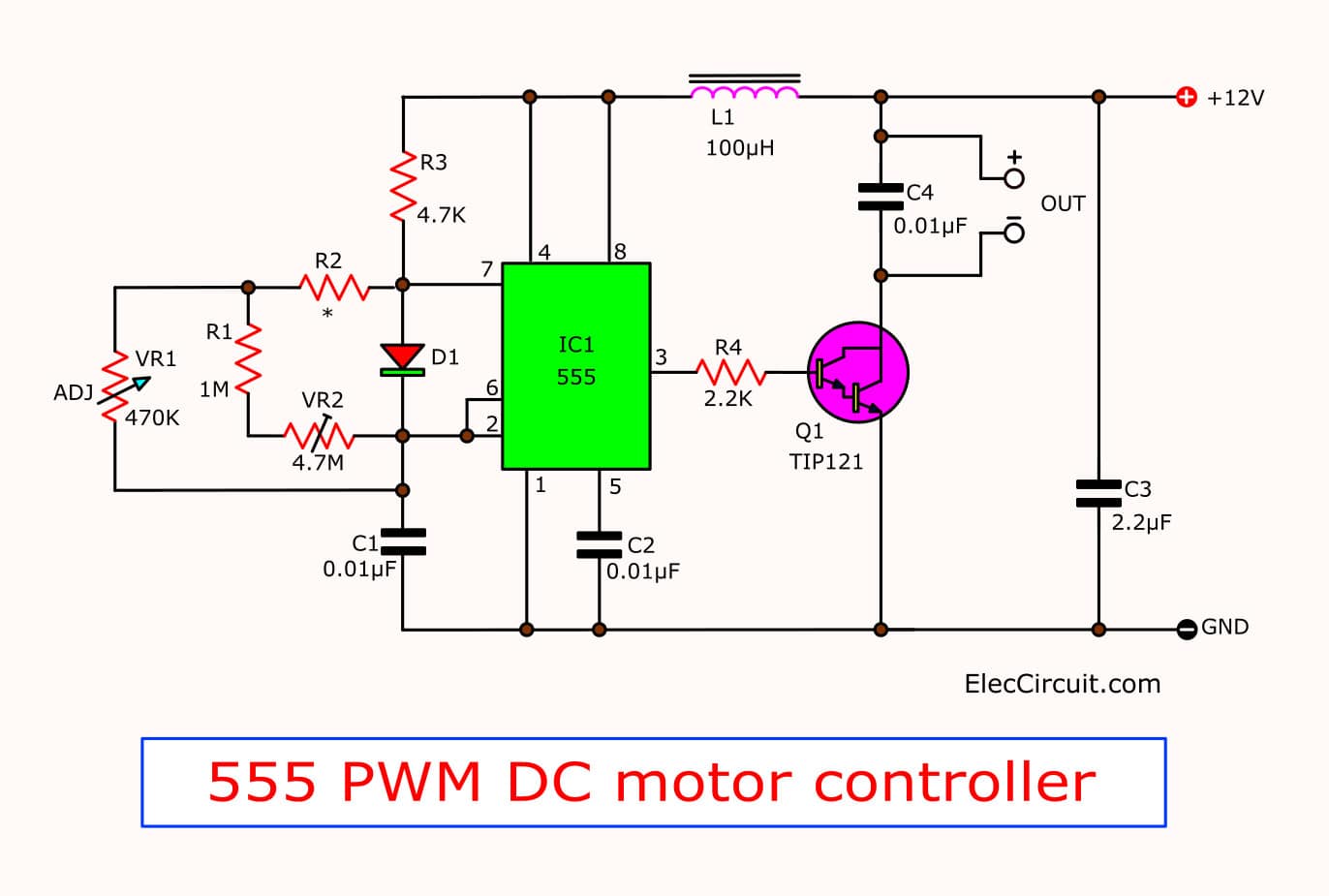
The Enviro-Tec “Generation 3 PWM” (G3 PWM) board provides a pulse-width modulated (PWM) signal to the EC motor ETI Fan Coil EC Motor Control Installation, Operation, and Maintenance. Rev. ..

EC motor wiring harness(es) open or.Designed Specifically for Fan Coils The EC motor used is specifically designed with fan coil horsepower requirements in mind (less than or equal to 1/4 HP). The new fan coil EC motors operate in a constant RPM mode compared to a constant airflow mode often associated with EC motor technology applied in Variable Air Volume boxes. Fan Coil EC Motor Control G3 PWM BOARD The Enviro-Tec “Generation 3 PWM” (G3 PWM) board provides a pulse-width modulated (PWM) signal to the EC motor to control fan speed.
The board is factory programmed to control the motor in either Three Speed (adjustable) mode or Proportional Control using a remote 2 – 10 V DC input signal.
EC fans and motors – ebm-papst A&NZ
EC Motor Wiring This publication contains supplemental wiring instructions for units incorporating EC motors. Carefully read this publication prior to any installation or maintenance procedure.
Loren Cook catalogs provide additional information describing the equipment, fan performance, available accessories, and specification data. For.
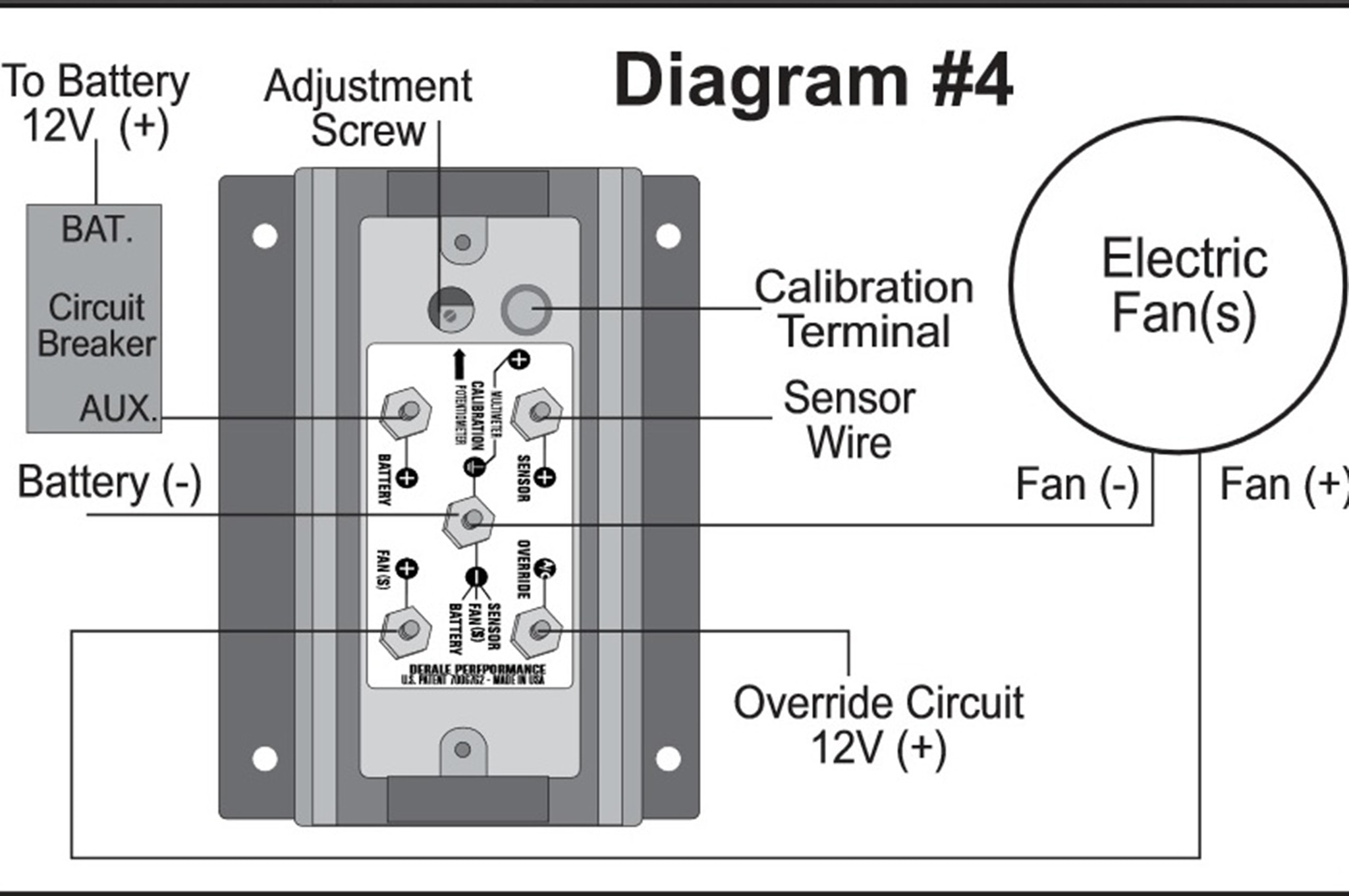
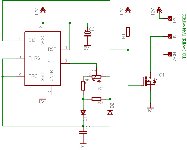
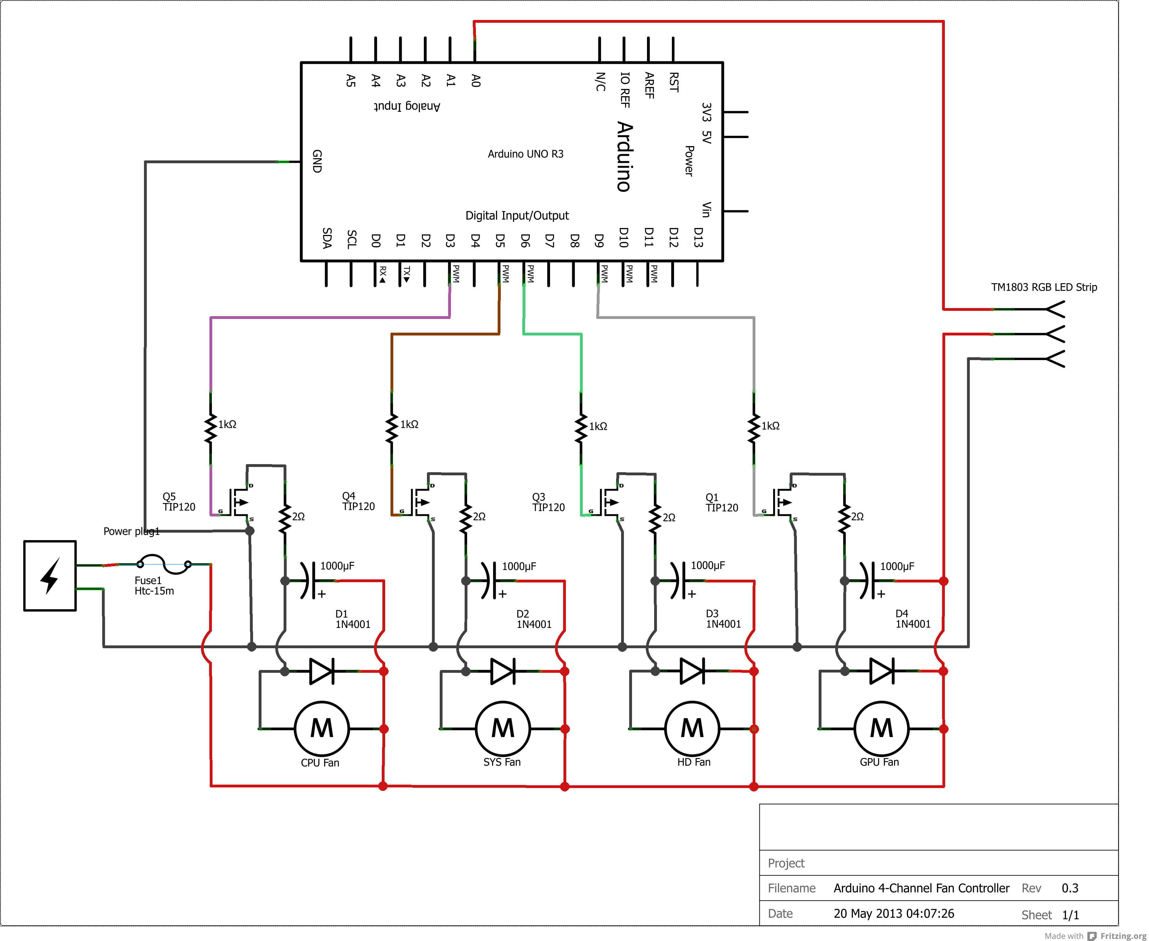
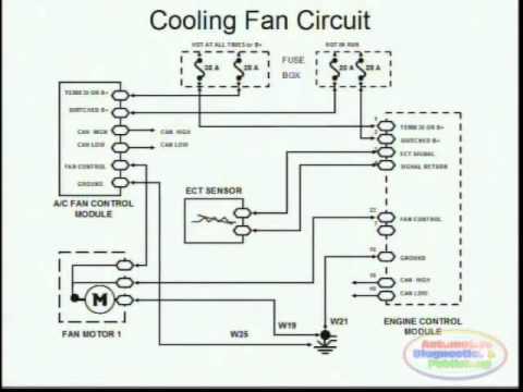
Suggested Electric Fan Wiring Diagrams Converting a 12 Volt Switch into a Ground Switch These diagrams show the use of relays, ON/OFF sensors, ON/OFF switches and ON/OFF fan controllers. Nothing here should be confused with the latest generation of PWM VARIABLE SPEED CONTROLLERS, which have much higher. ENERGY SAVING EC AXIAL FAN Energy Saving EC Fan VAC to VAC Input Voltage..
LCD EC fan controller (external 2fan)
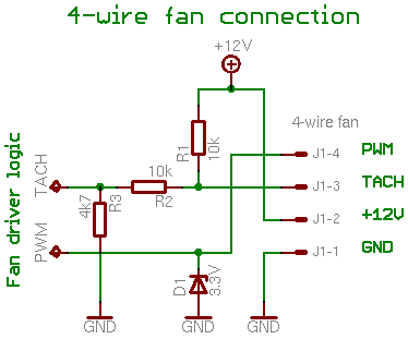
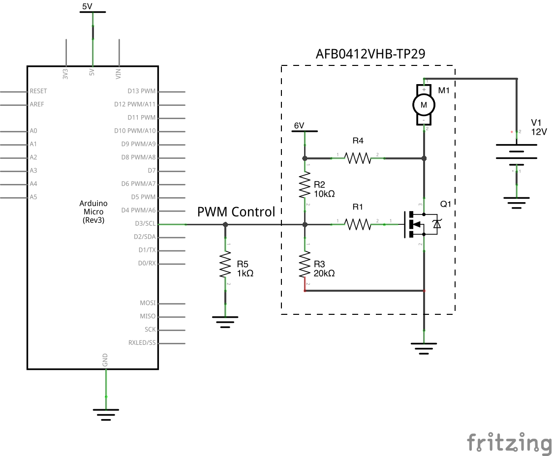
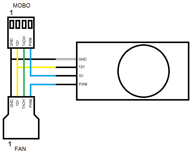
A rated voltage range of VAC~VAC(50/60Hz) Rotation Wiring Diagram AC Power supply BlackFAN PWM Black FAN Blue PWM Control Vst 0 to 5VDC Brown Duty Cycle 0~% 20k~30k Hz GND (0 V) AC Power supply Input Signal or or White RD or Yellow FG.EC Fans. – ppt video online downloadCatalogues & wiring diagrams of diverse purpose-built fans & motors -ebm-papst A&NZ Pty Ltd
