
An electronic transformer is a device used to convert electric energy from one voltage level to another. It is widely used in various applications, such as power supplies and audio equipment. This article will discuss the basic circuit diagram of an electronic transformer and how it functions.
The electronic transformer circuit diagram consists of several components, including a primary winding, a secondary winding, and a core. The primary winding is connected to the input voltage source, while the secondary winding is connected to the load or output. The core is made of a ferromagnetic material, such as iron, which helps increase the efficiency of the transformer.
The primary winding of the transformer is usually connected to an AC voltage source. When an alternating current passes through the primary winding, it creates a magnetic field in the core. This magnetic field then induces a voltage in the secondary winding, which is proportional to the ratio of the number of turns in the primary and secondary windings. As a result, the voltage at the output of the transformer is higher or lower than the input voltage, depending on the winding ratio.
In addition to the primary and secondary windings, the electronic transformer circuit diagram may also include other components, such as capacitors and diodes. These components are used to regulate the output voltage and protect the circuit from voltage spikes and fluctuations. The capacitors help smooth out the voltage waveform, while the diodes rectify the AC voltage to DC. This allows the transformer to provide a stable and reliable output voltage to the load.
In summary, the electronic transformer circuit diagram is a crucial component in various electronic devices. It allows for the conversion of voltage levels, making it possible to power different types of equipment. Understanding the basic circuit diagram of an electronic transformer can help in designing and troubleshooting electronic circuits.
What is an Electronic Transformer Circuit Diagram?
An electronic transformer circuit diagram is a visual representation of the components and connections used in an electronic transformer circuit. It shows how the different parts of the circuit are connected and how they function together to transform electrical energy.
The main purpose of an electronic transformer circuit diagram is to provide a clear and concise illustration of how the circuit works. It helps engineers and technicians understand the design and operation of the circuit, making it easier to troubleshoot and make any necessary changes or modifications.
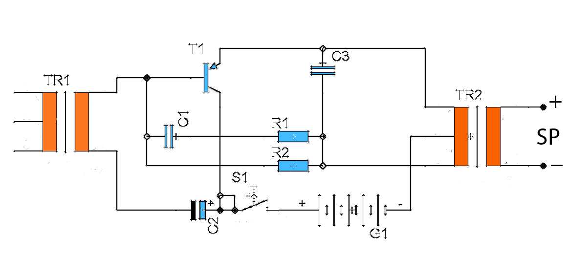
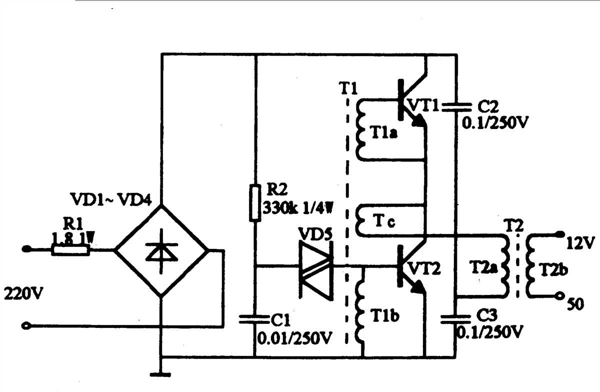
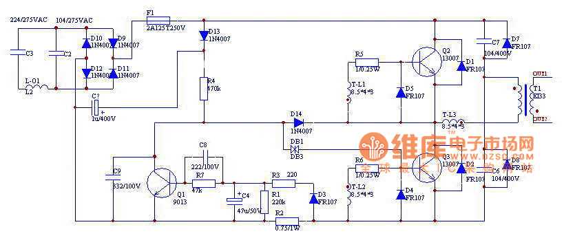
The diagram typically includes symbols to represent different components such as transistors, diodes, resistors, capacitors, and inductors. These symbols provide a standardized way of representing the various elements of a circuit and help to convey their function and connections.
An electronic transformer circuit diagram may also include labels or annotations to provide additional information about the circuit, such as voltage ratings, values of components, and specific pin configurations.
The diagram may be drawn using specialized software or created manually using pen and paper. It can be printed or displayed electronically, making it easily accessible for reference during circuit assembly, testing, and troubleshooting.
Overall, an electronic transformer circuit diagram serves as a valuable tool for understanding and working with electronic transformers. It provides a visual representation of the circuit’s design and helps in analyzing its functionality and performance.
Understanding the Basics of Electronic Transformers
Electronic transformers are devices used in electronic circuits to step up or step down the voltage levels. They are commonly used in power supplies, audio amplifiers, and other electronic devices. Understanding the basics of electronic transformers can help you design and troubleshoot circuits that use them.
An electronic transformer consists of two or more coils of wire wound around a common core. The primary coil is connected to the input voltage source, while the secondary coil is connected to the load. When an alternating current passes through the primary coil, it creates a magnetic field in the core. This magnetic field induces a voltage in the secondary coil, which is then utilized by the load.
One of the key parameters to consider when designing or selecting an electronic transformer is the turns ratio. The turns ratio is the ratio of the number of turns in the primary coil to the number of turns in the secondary coil. It determines the voltage transformation ratio of the transformer. For example, a transformer with a turns ratio of 1:2 will step up the voltage by a factor of 2.
Electronic transformers also have certain limitations and considerations. They have a maximum power rating, which determines the amount of power they can handle without overheating. It is important to select a transformer that can handle the power requirements of your circuit. Additionally, transformers may introduce losses and impedance matching issues, which should be carefully considered during the design process.
In conclusion, electronic transformers are essential components in many electronic circuits. They provide voltage transformation and play a crucial role in power supplies and audio amplifiers. By understanding their basic principles and considerations, you can effectively design and troubleshoot circuits that use electronic transformers.
Components used in an Electronic Transformer Circuit
An electronic transformer circuit is a device used to step up or step down the voltage level in an electrical system. It consists of several components that work together to convert the input voltage to the desired output voltage. Let’s take a closer look at some of the main components used in an electronic transformer circuit:
1. Transformer
The transformer is the heart of the electronic transformer circuit. It is a device that consists of two or more coils of wire wound around a magnetic core. The primary coil receives the input voltage, while the secondary coil delivers the output voltage. The turns ratio of the coils determines the voltage transformation ratio of the transformer.
2. Diodes
Diodes are essential components in an electronic transformer circuit as they allow the flow of current in one direction. They are typically used in rectification circuits to convert alternating current (AC) to direct current (DC). The diodes also help protect other components from reverse voltage and prevent them from getting damaged.
3. Capacitors
Capacitors are used in electronic transformer circuits to store and release electrical energy. They are commonly used in filter circuits to smooth out the output voltage and reduce any unwanted ripple. Capacitors can also be used for power factor correction and voltage regulation.
4. Transistors
Transistors are semiconductor devices that amplify or switch electronic signals and currents. In an electronic transformer circuit, transistors are often used in the control circuitry to regulate the output voltage or current. They can also be used to switch the primary coil on and off, allowing for finer control over the voltage transformation.
5. Resistors
Resistors are passive electronic components that limit the flow of current in a circuit. In an electronic transformer circuit, resistors are often used to provide voltage division or current limiting. They can also be used in the control circuitry to set the desired output voltage or current levels.
6. Inductors
Inductors are passive components that store energy in a magnetic field. They are often used in electronic transformer circuits to filter out high-frequency noise or to provide additional impedance matching. Inductors can help stabilize the output voltage and improve overall circuit performance.
These are just a few of the main components used in an electronic transformer circuit. Depending on the specific requirements of the circuit, other components such as switches, voltage regulators, and integrated circuits may also be used to enhance the functionality and performance of the circuit.
Working Principle of an Electronic Transformer Circuit
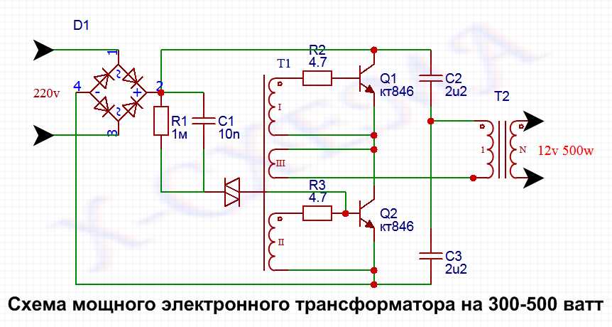
An electronic transformer circuit is a type of power converter that converts electrical energy from one voltage level to another, without using traditional magnetic transformers. It operates based on the principle of high-frequency switching.
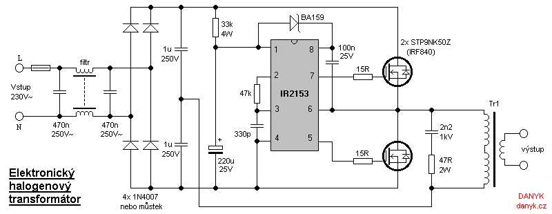
In an electronic transformer circuit, the input voltage is first converted into high-frequency AC voltage using a high-frequency oscillator. This oscillator generates a square wave signal, which is then fed into a power semiconductor device such as an insulated gate bipolar transistor (IGBT) or a metal–oxide–semiconductor field-effect transistor (MOSFET).
The high-frequency AC voltage is then applied to a high-frequency transformer, which typically consists of a ferrite core and multiple winding coils. The primary winding of the transformer is connected to the power semiconductor device, and the secondary winding is connected to the load.
When the power semiconductor device is switched on, it allows the high-frequency AC voltage to flow through the primary winding of the transformer. This creates a magnetic field in the core, which induces a voltage in the secondary winding. The voltage induced in the secondary winding is proportional to the turns ratio of the transformer.
The high-frequency AC voltage from the secondary winding is then rectified and filtered to obtain the desired output voltage. This rectification and filtering process is typically performed using diodes and capacitors.
The main advantage of an electronic transformer circuit is its compact size and high efficiency compared to traditional magnetic transformers. It is commonly used in electronic devices such as LED drivers, power supplies, and inverters.
Advantages of Electronic Transformer Circuits
Electronic transformer circuits have several advantages over traditional transformer circuits. These advantages include:
- Efficiency: Electronic transformer circuits are more efficient compared to traditional transformer circuits. They can operate at higher frequencies, which reduces losses and increases overall efficiency. This is especially beneficial in applications where energy efficiency is a priority, such as in power supplies for consumer electronics.
- Compact Size: Electronic transformer circuits are generally smaller and more compact compared to traditional transformer circuits. This is because they do not require a large iron core and their components can be integrated into a single chip or module. This compact size is advantageous in space-limited applications, such as in portable devices or embedded systems.
- Lightweight: Due to their compact size and absence of a heavy iron core, electronic transformer circuits are significantly lighter compared to traditional transformer circuits. This is particularly useful in applications that require portability, such as in laptops, smartphones, or electric vehicles.
- Flexible Voltage Regulation: Electronic transformer circuits provide better voltage regulation compared to traditional transformer circuits. They can easily adjust the output voltage based on the input voltage or load variations. This flexibility in voltage regulation makes electronic transformer circuits suitable for a wide range of applications, from low power devices to high power industrial systems.
- Enhanced Control and Protection: Electronic transformer circuits offer advanced control and protection features. They can incorporate various control mechanisms, such as feedback loops and digital signal processing, to enhance the performance and reliability of the circuit. Additionally, electronic transformer circuits can include protection mechanisms, such as overcurrent and overvoltage protection, to safeguard the circuit and connected devices.
In conclusion, electronic transformer circuits bring several advantages over traditional transformer circuits, including higher efficiency, compact size, lightweight, flexible voltage regulation, and enhanced control and protection capabilities. These advantages make electronic transformer circuits a preferred choice in many modern electronic applications.
Applications of Electronic Transformer Circuits
The electronic transformer circuit has several applications across various industries. Some of the common applications are:
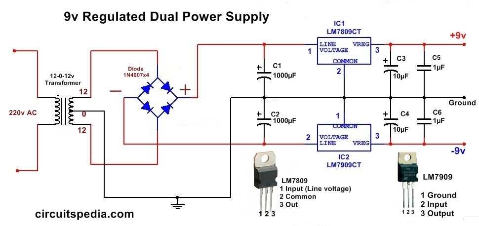
- Power Supply: Electronic transformer circuits are commonly used in power supply applications. They can efficiently step-up or step-down the voltage levels to provide the desired power output. These circuits are widely used in industries, homes, and electronic devices to ensure a stable and reliable power supply.
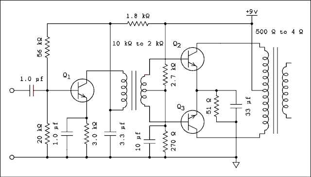
- Audio Amplifiers: Electronic transformer circuits are also used in audio amplifiers to provide impedance matching between different audio components. They can transform the impedance level between audio devices, allowing for efficient transfer of audio signals without loss of quality. This helps in improving the overall sound quality and performance of audio systems.
- Communication Systems: The electronic transformer circuit plays a significant role in communication systems. It is used to match the impedance level between different stages of the communication system, ensuring efficient transmission of signals without distortion. These circuits are widely used in telecommunication systems, radio transmitters, and receivers.
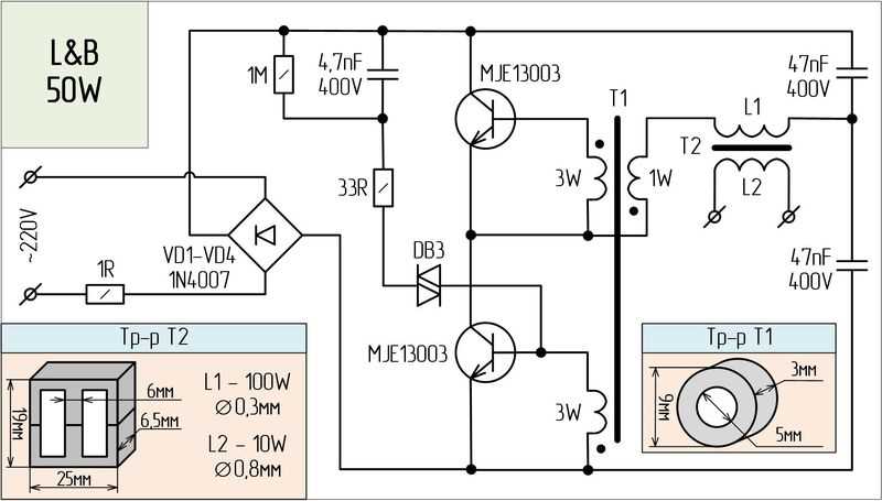
- Lighting Systems: Electronic transformer circuits are used in lighting systems, especially in LED and fluorescent lighting applications. They help in converting the input voltage to the desired level for efficient operation of the lighting system. These circuits also provide the necessary voltage and current regulation for optimum performance and energy efficiency.
- Electric Vehicles: Electronic transformer circuits are employed in electric vehicle charging systems. They help in converting the grid-supplied AC voltage to the required DC voltage for charging the vehicle’s battery. These circuits also provide necessary control and protection features to ensure safe and efficient charging of electric vehicles.
In conclusion, electronic transformer circuits find extensive applications in power supply, audio amplifiers, communication systems, lighting systems, and electric vehicles. They play a crucial role in ensuring efficient voltage conversions, impedance matching, and signal transmission in various electronic systems and devices.