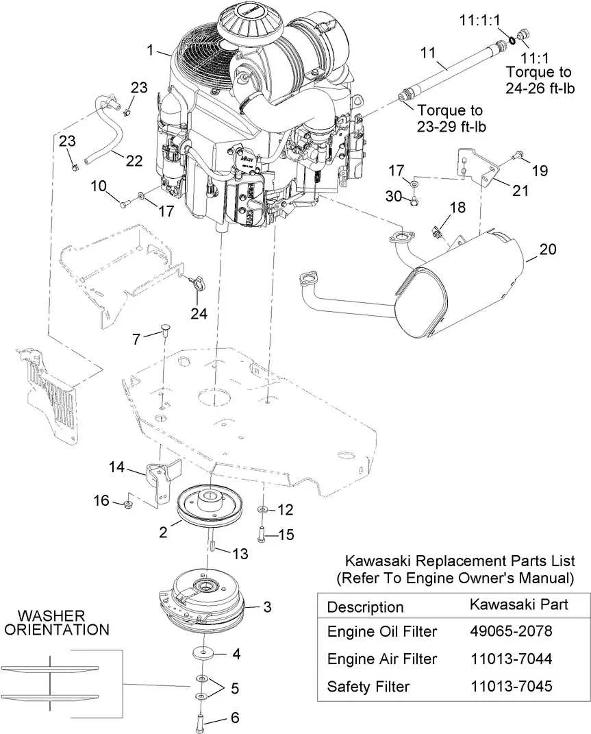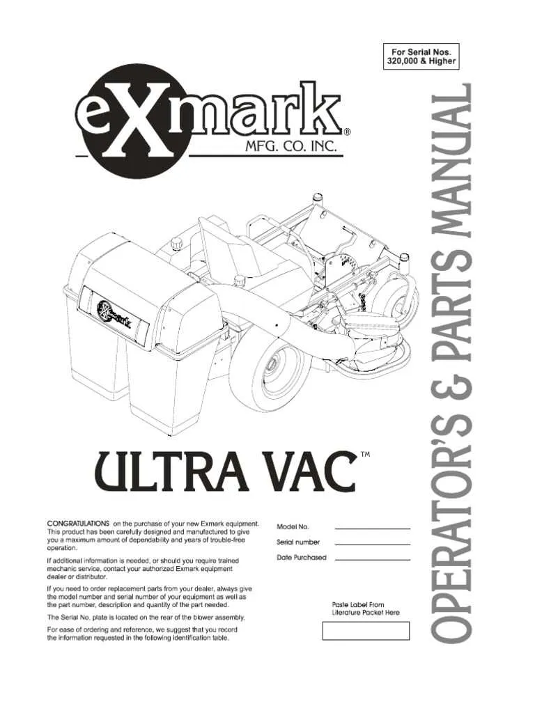
For efficient repair or maintenance, it is crucial to have a clear overview of the 60-inch zero-turn mower’s mechanical layout. This helps identify each individual element, from the cutting deck to the wheel assembly. Having precise information allows you to quickly diagnose issues and make informed decisions about replacements or adjustments.
Refer to a detailed visual map of the mower’s structure to pinpoint the exact placement of key components. It is particularly useful for troubleshooting, such as when the engine malfunctions or when parts become loose over time. Knowing the exact configuration also speeds up assembly and disassembly tasks, ensuring that you don’t miss any vital connections.
Ensure you familiarize yourself with the major sections: the drive system, steering controls, and engine linkages. The correct identification of each part is essential for avoiding errors during repairs and maintaining the mower’s optimal performance. Regularly updating your understanding of these components can save time and prevent costly mistakes.
Tip: Keep a high-quality manual nearby for reference when working with the mower’s mechanism. An up-to-date guide will always provide the most accurate configuration for parts placement and function.
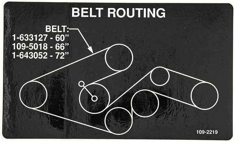
As you examine each segment, note that even small adjustments can have significant effects on overall operation. For instance, improperly aligned pulleys or misaligned belts can cause the mower to perform poorly or even damage the engine. Be proactive in inspecting these areas during routine checks.
Exmark 60 Lazer Z Components Overview

For optimal performance, always ensure the correct identification of each mechanical element. The primary assembly includes the engine, deck, transmission, and wheels, each crucial for efficient operation. The engine components consist of the fuel system, ignition system, and air intake, which must be regularly checked for any signs of wear or clogging. Ensure that the engine mounts are securely fastened to avoid unnecessary vibration during use.
The cutting deck is integral for achieving a precise mow, and the blades should be sharp and balanced at all times. Pay attention to the deck belt tension, as it directly affects blade performance. If you notice uneven cutting or excessive noise, inspect the deck for any obstructions or damage to the pulleys.
The transmission system, responsible for speed control and movement, should be examined periodically for fluid levels and leaks. If the drive system is sluggish, it might be due to worn-out drive belts or faulty hydraulic components. Keep the system lubricated and replace belts as needed to maintain smooth functionality.
Finally, inspect the wheel assemblies for any signs of damage or misalignment. Tire pressure is critical, as it affects both the machine’s stability and maneuverability. A well-maintained wheel assembly ensures smoother operation and extends the lifespan of the mower.
Understanding Key Components of the 60-inch Z-Series Mower

To ensure efficient operation and longevity of your 60-inch Z-series mower, it’s essential to familiarize yourself with its critical components. Each part plays a crucial role in enhancing performance and ease of use. Below are the primary sections to focus on:
- Hydraulic System: This system is integral to the mower’s ability to maneuver and adjust cutting heights. Regular maintenance is required to keep the fluid levels and connections secure.
- Deck Assembly: The cutting deck is where precision meets durability. Pay attention to the condition of the blades, spindle assemblies, and anti-scalp wheels. A well-maintained deck guarantees a uniform cut.
- Drive System: The transmission connects the engine power to the wheels. Check the belts and pulleys regularly to avoid slippage, ensuring the mower responds promptly to throttle input.
- Engine: Performance heavily depends on engine maintenance. Ensure the air filter is clean, oil is changed regularly, and spark plugs are in good condition.
- Chassis and Frame: The frame supports all other components. Inspect the structure for any signs of wear or cracks, especially after heavy use. Regular checks can prevent costly repairs.
By understanding and maintaining these components, you can improve the mower’s overall performance and extend its service life.
How to Identify and Replace Faulty Components on a 60-inch Mower
Start by inspecting the engine. A common issue is a misfiring or hard-starting motor. If the engine cranks but doesn’t start, check the spark plugs first. Replace them if they’re worn or dirty, as this can improve performance. If the engine runs rough, check the fuel filter for blockages and replace it if necessary. Clean or replace the air filter to ensure proper airflow.
Next, inspect the deck for damage or uneven cutting. A common cause of poor performance is a bent blade. Ensure the blades are sharp and free of any nicks. If the deck vibrates excessively or leaves an uneven cut, inspect the spindle bearings for wear. Replace any faulty spindles or bearings to restore proper function.
The drive system should also be checked regularly. If the mower is slow to engage or stops unexpectedly, the belts may be worn. Replace any frayed or stretched belts to maintain optimal performance. If the transmission is sluggish, consider checking the fluid level and replacing it if it’s low or contaminated.
Don’t overlook the steering system. If the mower pulls to one side or is difficult to maneuver, inspect the steering linkage and adjust if needed. If any parts are worn out, replace them immediately to maintain smooth operation.
Lastly, ensure the electrical components are in good condition. A malfunctioning battery or wiring can lead to starting issues. Check for corrosion on the battery terminals and clean them. If the battery doesn’t hold a charge, replace it with a compatible one. For any electrical shorts or issues, trace the wiring and replace damaged connectors.
Step-by-Step Guide to Interpreting the Exmark 60 Lazer Z Parts Diagram
Start by identifying the section of the equipment you’re working on. Focus on the key components like the engine, transmission, or deck to break down the larger assembly into smaller, more manageable parts.
Next, locate the part numbers listed on the diagram. These numbers are crucial for ordering replacements. Be sure to cross-check the part number with your user manual to confirm compatibility with your model.
Pay attention to the orientation of parts. Understanding how components fit together is essential. For instance, some parts are designed to fit in a specific direction, so ensure you’re positioning them correctly to avoid assembly issues.
Zoom in on detailed labels next to each component. These typically provide information about specific sizes, materials, or features that are essential when replacing worn-out parts.
When looking at the assembly layout, note the connections between parts. For example, bolts, nuts, and washers are often shown as individual elements, which you must align properly to ensure secure fitting.
Check for assembly instructions or arrows indicating movement or alignment. These annotations help clarify how parts move relative to each other during operation, which is vital for maintenance and repair tasks.
If there are color-coded sections or grouped parts, use these visual clues to understand how different parts interact. This can simplify the process of identifying the right piece or understanding the assembly sequence.
Finally, consult any additional reference materials, like online forums or videos, to see if others have encountered similar issues or interpretations. Visual guides can sometimes clarify the most confusing diagrams, providing you with extra confidence in your repair work.