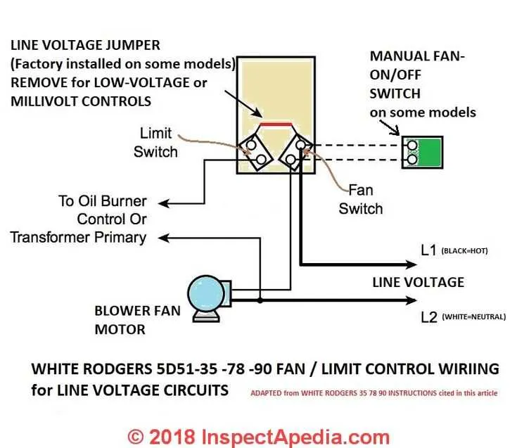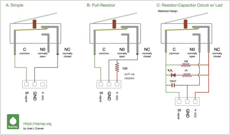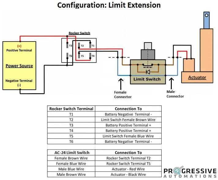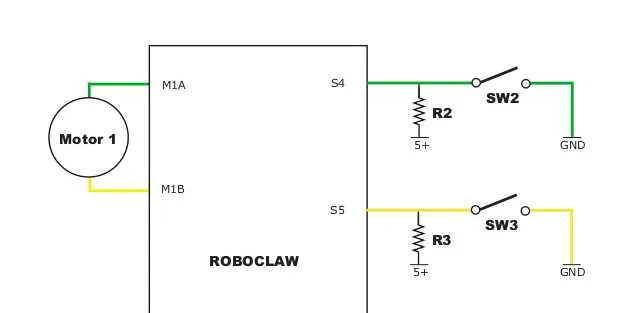
For effective integration of position sensors in your automation setup, ensure that each component is properly connected to prevent faults and ensure reliability. The first step is to correctly assign terminals, typically focusing on NO (Normally Open) and NC (Normally Closed) contacts. This ensures proper signal flow when the actuator reaches the desired position.
Terminal identification is crucial. Pinouts for these components are usually clearly marked: the common terminal connects to the signal input of the controller, while the other two terminals correspond to the normally open and closed circuits. In most configurations, you’ll have a direct line to the relay or PLC, so it’s essential to verify that connections match the controller’s specifications to avoid miscommunication.
Another key point is the grounding system. Make sure that the ground is solid, typically through a dedicated earth ground, to avoid interference. Voltage ratings must be adhered to, particularly if the sensor is rated for high current; using an incorrect gauge wire can result in overheating or failure of the system.
Finally, always conduct a continuity test after installation. This ensures that the path is clear and that no short circuits or open connections exist, which could impair the system’s response time or accuracy in operation.
Electrical Connection Setup for Mechanical Position Sensors

For optimal functionality, connect the actuator terminals to the sensor’s contact points, ensuring proper orientation. When using an N.O. (Normally Open) configuration, establish a direct link between the circuit and the device that requires activation. If employing an N.C. (Normally Closed) setup, ensure the circuit breaks when the sensor reaches its designated point.
For devices that operate under higher currents, opt for cables with a robust insulation rating to prevent wear and electrical failures. Use shielded cables to reduce interference, especially when dealing with high-frequency environments. Tighten all connectors securely to avoid any signal loss.
In applications requiring long-distance signal transmission, employ a relay or intermediary module to maintain signal integrity. Ensure the power supply matches the sensor’s voltage and current specifications to avoid damage to internal components.
To prevent accidental activation, place the sensor on a stable, non-vibrating surface. Calibration of the detection range should be done according to the manufacturer’s specifications to ensure precise operation. Regular maintenance checks on connectors, wiring, and insulation will prolong the lifespan of the equipment.
Connections for Different Types of Actuators

For mechanical actuators, connect the common terminal to the power supply, the normally open terminal to the load, and the normally closed terminal to ground. Ensure proper insulation to avoid short circuits.
In the case of float-type actuators, connect the input terminals to a relay. The common terminal links to the system power, while the normally open terminal is used for load control. The normally closed terminal serves as an alternative safety mechanism if the actuator malfunctions.
For roller-type actuators, use a two-wire connection. One wire connects to the ground, while the other goes to the relay for system activation. Maintain a minimum clearance to avoid mechanical interference with moving parts.
For pressure-sensitive types, use the pressure-sensitive terminals to connect with the relay module. The circuit should be secured with an insulated terminal to ensure accurate feedback for system regulation.
In case of electric actuators with a higher current rating, always use thick gauge wires to prevent overheating. The common terminal connects to the supply voltage, while the normally open terminal connects to the load, and the normally closed terminal provides backup control for safety shutdowns.
How to Select the Correct Wire Gauge for Limit Switches
For reliable operation, use a wire size that matches the current rating of the device and the distance the power will travel. For most applications, 18 to 22 AWG is typical, with 18 AWG for longer runs and higher currents.
For loads under 5 amps, 22 AWG is sufficient for shorter distances (up to 10 feet). For longer distances or higher amperages (above 5 amps), consider thicker gauges like 18 or 16 AWG. Always ensure the wire’s current rating is higher than the device’s demand.
Ensure that the insulation rating matches the operating environment, especially in high-temperature or wet conditions. Choose wires with proper insulation materials like PVC or Teflon, which can handle the specific environment and provide protection from wear or chemical exposure.
Additionally, account for voltage drop in longer cable runs. For example, if running over 100 feet, it’s advisable to use a lower gauge to minimize loss. Factor in both the current rating and the environmental conditions to select the best option.
Always follow manufacturer recommendations and safety standards to avoid overheating, poor performance, or safety hazards.
Troubleshooting Common Electrical Issues in Actuator Circuits

Verify continuity in the circuit with a multimeter. Ensure there is no break in the path between terminals. If there’s an open connection, inspect for loose or corroded contacts that may interfere with proper operation.
Check for incorrect polarity. Reversing the connection can cause the system to malfunction. Ensure that the positive and negative terminals are properly connected as per the manufacturer’s instructions.
Inspect for excessive voltage drop. Use a voltmeter to confirm that the voltage at each component matches the expected values. Significant voltage drop can indicate poor connections or an undersized power supply.
Evaluate the load capacity. If the system is drawing more current than the circuit can handle, components can overheat and fail. Ensure the conductor gauge and protection devices are appropriate for the load.
- Measure the current with a clamp meter to verify if it exceeds the system’s rated capacity.
- Inspect fuses or circuit breakers to ensure they are rated correctly.
Examine for external interference. High-powered devices nearby, such as motors or large transformers, may induce unwanted electrical noise. Use shielding or reroute wires to minimize impact.
Ensure the actuator’s mechanical components are properly aligned. Misalignment can strain the system, causing inconsistent electrical feedback or triggering false signals. Check for wear and tear or misplacement of parts.
Verify the grounding of the circuit. Improper grounding can lead to erratic operation or failure. Test the ground connection with a continuity tester to ensure a secure path to earth.
Lastly, confirm the component specifications match the system requirements. Using parts with incompatible voltage ratings or current capacities will cause instability and damage over time.