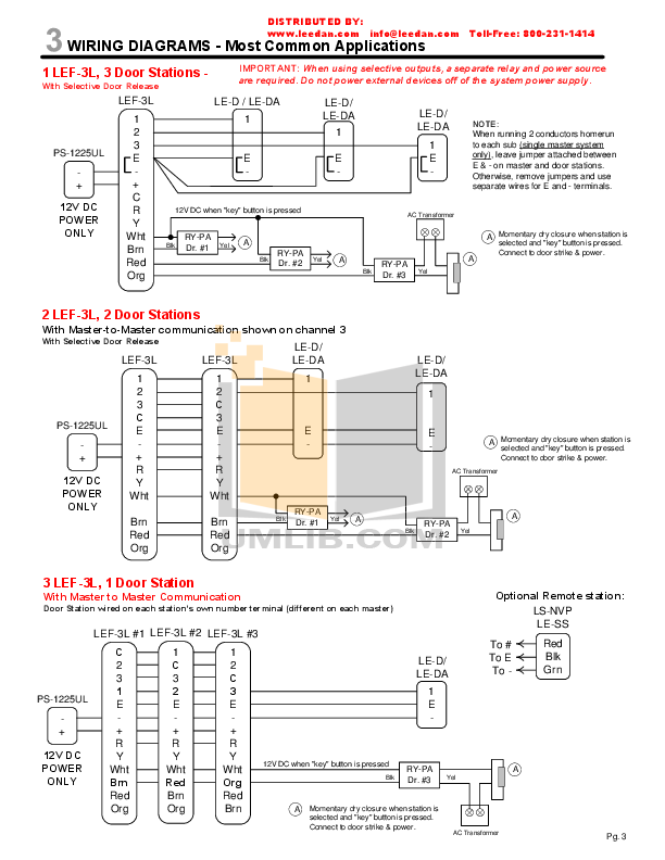
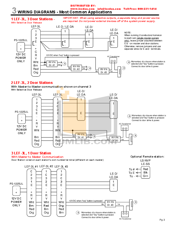
Dual Vestibule Connection Diagram AC Door Strike Operation. .
Connect Mircom M/M Door Strike to amplifier terminals L1 and L2 for DC (silent) .. A Fire Alarm system must be installed in accordance with all the applicable codes and Alarm Notification Appliances such as sirens, bells, horns, or strobes may not.
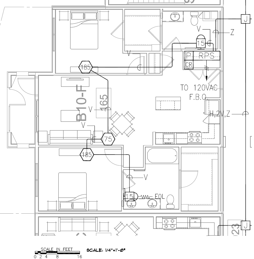
SPEAKER STROBE CEILING MOUNTED UNIT FIRE ALARM DEVICE MOUNTING HEIGHTS SHALL COMPLY WITH ALL ANSI , NFPA. 72 AND MANUAL PULL STATION: 48″ A.F.F.
TO CENTER . NO T-TAPPING CIRCUITS FROM FACPS: REQUIRED EOL, CIRCUITS FROM AMPLIFIERS/DGPS: REQUIRED EOL. Amplifier.
• 25 or 70 VRMS Field Selectable Class A/B Speaker Circuit Microprocessor based and Networked Fire Alarm Systems. • 3 Minute Backup Amp Switching card Strobe Circuit w . interrupt the broadcast with a manual page.
smoke detectors, heat detectors, manual pull stations, audible warning devices Please note that: • Strobes can, under certain circumstances, cause seizures. ATPC Amplifier Terminal Panel Cabinet • ATP Amplifier ..
information on the placement and layout of strobes for fire alarm signaling.The Fire Panel Forums. The Fire Alarm Authority.
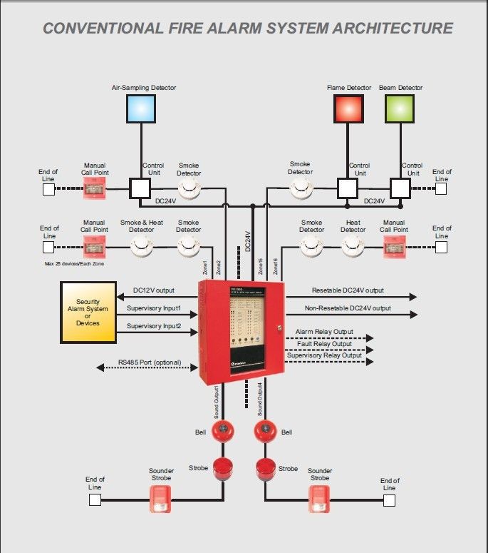
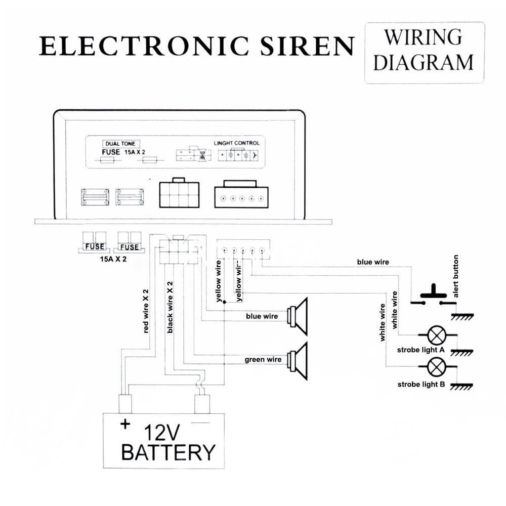
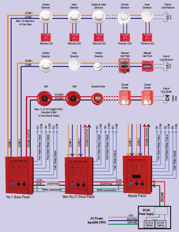
This diagram shows the basic wiring of two pull stations and two horn/strobes to a power supply: Notice the difference between a 2-wire and 4-wire horn/strobe. On a 4-wire device, the horn and strobe are powered separately. Simply jump one set of terminals to the other two power both at once.
1. Install manual fire-alarm box in the normal path of egress within 60 inches ( mm) of the exit doorway.
2. Mount manual fire-alarm box on a background of a contrasting color.
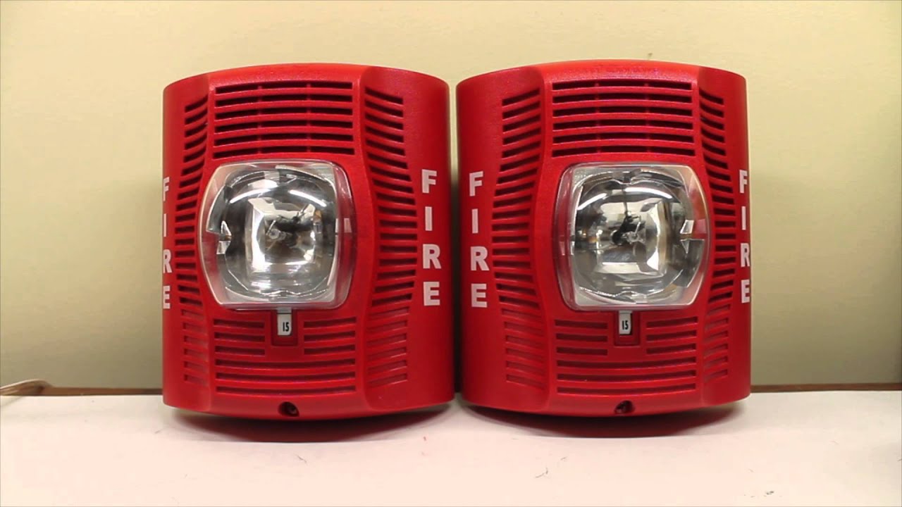
3. The operable part of manual fire-alarm box shall be between 42 inches ( . The Genesis Speaker-Strobe is a fire alarm notification appliance designed for indoor walls.
See Table 1 for a list of Connect the speaker and strobe terminals to the signal circuit field wiring. For the unit to function properly, observe polarity.
See Figure 5. Find great deals on eBay for fire alarm speaker strobe.
Shop with confidence. Skip to main content. eBay: SIEMENS WALL FIRE ALARM STROBE SPEAKER 24VDC SET-MC-W *NEW* See more like this.
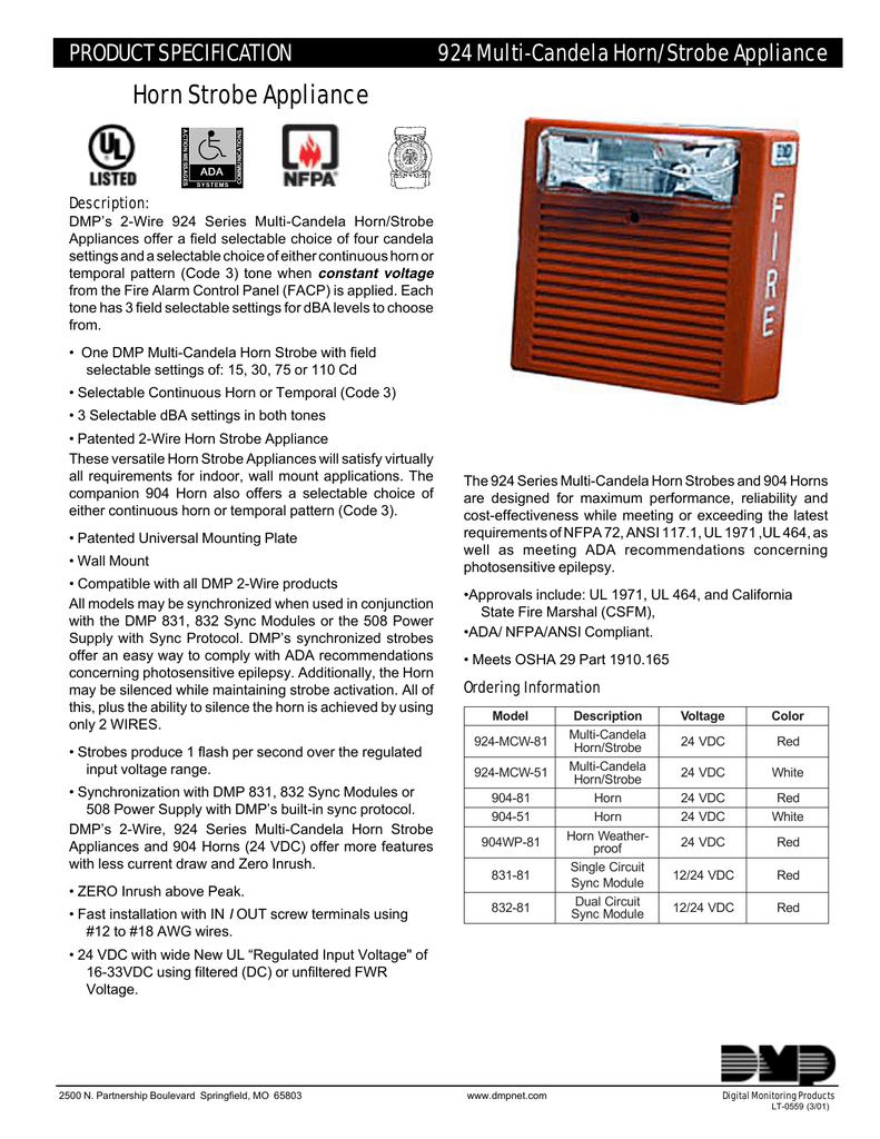
System Sensor SpectrAlert Advance SPSR Wall Speaker Strobe Fire Alarm, White. Brand New.
Burglar Alarm Cable Camera / CCTV Cable Fire Alarm Cables Telephone Cables International Cables Healthcare Cables Zettler Non-Plenum Plenum EZCare Non-Plenum Plenum Executone Non-Plenum Plenum LAN / Network Cables. Tools Conduit Calculator Voltage Loss Formulas Wiring Diagrams by Manufacturer Conversion Tables AWG Chart National Electric Code.Fire Alarm Product Literature | National Time & SignalCWSI :: The future of wireless fire alarm technology has arrived.
