
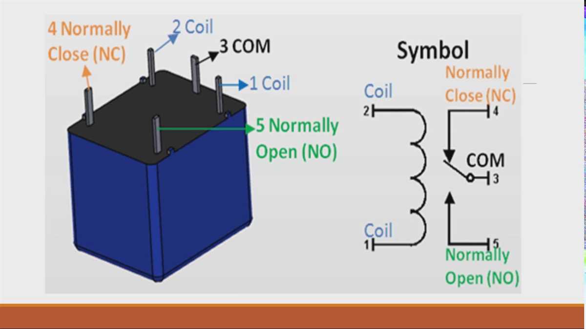
A five-pin relay diagram is a graphical representation of the wiring and connections within a five-pin relay. Relays are electromechanical devices that are typically used to control electrical circuits. They consist of a coil, as well as contacts that open and close to allow or interrupt the flow of current.
The five-pin relay is a common type of relay that is widely used in automotive applications. It is often used to control electrical devices such as lights, motors, and solenoids. The five pins on the relay are labeled with numbers or letters to indicate their specific function.
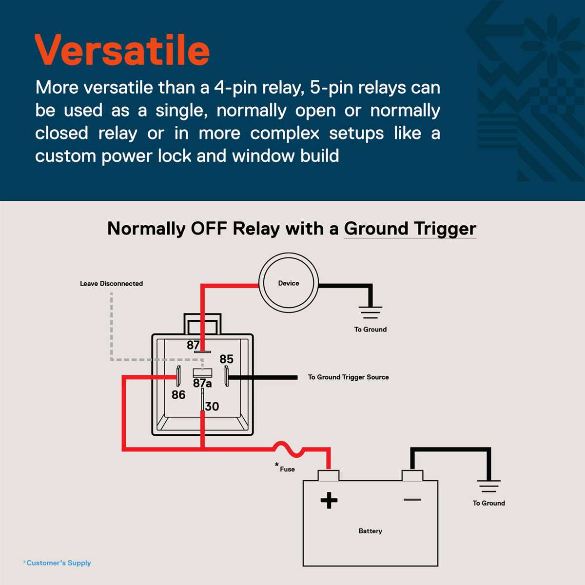
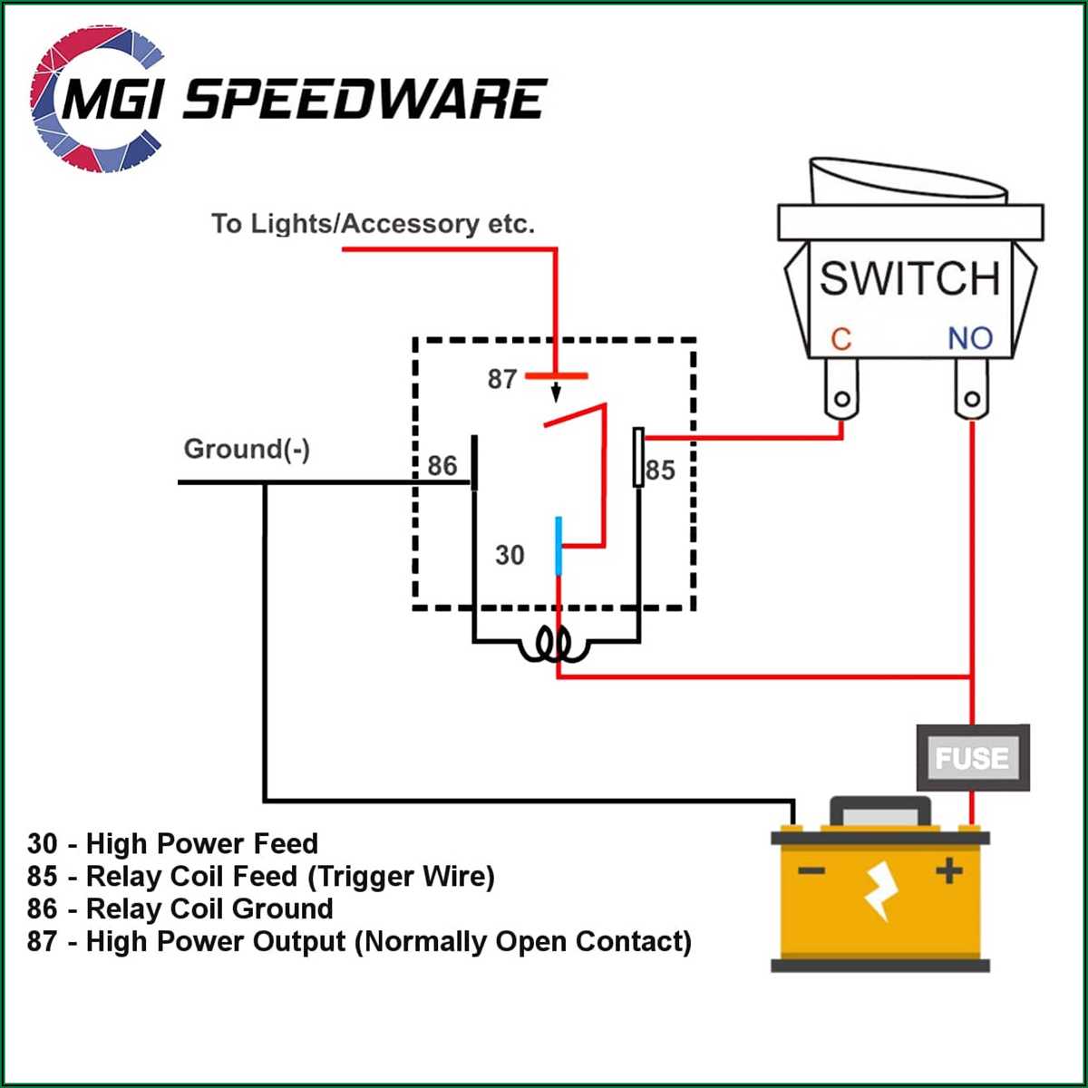
In a five-pin relay diagram, each pin is assigned a specific task. Pin 30 is the common pin, which is the point where the current from the power source is split to power the controlled devices. Pin 87 is the normally open (NO) contact, which is used to allow the current to flow through the relay when the coil is energized.
Pin 87a is the normally closed (NC) contact, which allows the current to flow through the relay when the coil is de-energized. Pin 86 is the coil pin, which is connected to a power source to energize the coil and activate the relay. Finally, pin 85 is the coil ground pin, which is connected to the ground to complete the circuit.
In conclusion, a five-pin relay diagram provides a graphical representation of the wiring and connections within a five-pin relay. It is a useful tool for understanding the functionality and operation of the relay, as well as for troubleshooting and repairing electrical circuits that involve relays. Understanding the pin assignments and their specific functions is essential for successfully using and maintaining a five-pin relay.
What is a Five Pin Relay?
A five pin relay is an electrical device used to control the flow of electrical current in a circuit. It is commonly used in automotive and industrial applications, where it is used to switch high currents using a low power signal. The five pin relay is called so because it has five pins that are used to connect it to the circuit.
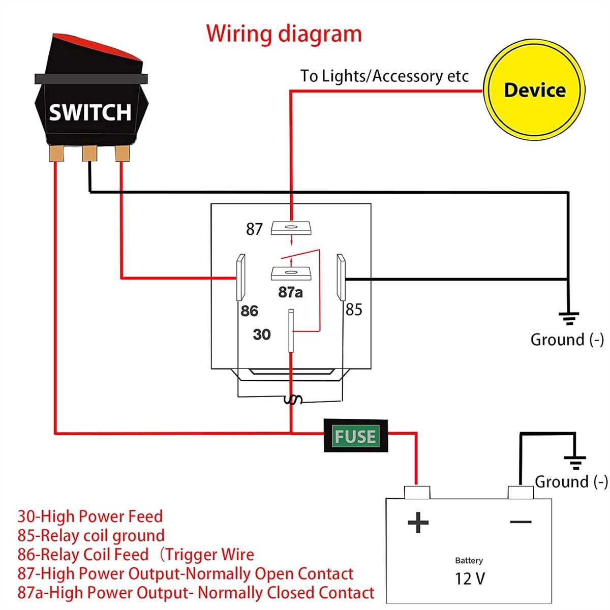
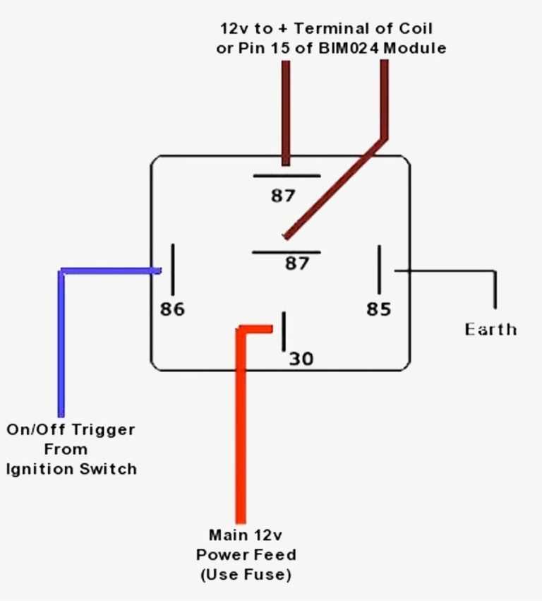
The pins on a five pin relay are usually labeled as follows: pin 30, pin 85, pin 86, pin 87, and pin 87a. Pin 30 is the common pin, which is connected to the power source. Pin 85 is the trigger pin, which receives the control signal to activate the relay. Pin 86 is the ground pin, which is connected to the negative terminal of the power source. Pins 87 and 87a are the output pins, which are connected to the device or load that needs to be controlled.
The five pin relay works by using an electromagnet to control the flow of current. When the control signal is received at pin 85, the electromagnet is activated, which then pulls the switch inside the relay, allowing current to flow from pin 30 to either pin 87 or pin 87a, depending on the relay’s configuration. This allows the relay to switch high currents using a low power signal, providing protection and control in various electrical circuits.
Overall, the five pin relay is a versatile and widely used component in electrical and electronic systems. Its ability to control high currents makes it suitable for a range of applications, including automotive lighting, motors, fans, and other electrical devices. By understanding how the pins on a five pin relay are connected and how it works, it becomes easier to design and troubleshoot circuits using this important electrical component.
Understanding the Basics of a Five Pin Relay
A five pin relay is an electrical device that allows a low power signal to control a high power circuit. It is commonly used in automotive applications to control various electrical components such as lights, motors, and solenoids. Understanding the basics of a five pin relay can help in troubleshooting and repairing electrical systems.
Pin Configuration: A typical five pin relay consists of five terminals labeled 85, 86, 87, 87a, and 30. Terminal 85 is connected to the control signal, while terminal 86 is connected to a ground or negative source. Terminal 87 is the main output terminal, and 87a is a secondary output terminal. Terminal 30 is the input or power source.
Working Principle: When a control signal is applied to terminal 85, it energizes the electromagnetic coil inside the relay. This causes the relay’s internal contacts to close, connecting terminal 30 to terminal 87. This allows the high power circuit to be energized and function as intended. When the control signal is removed, the relay returns to its default state, with terminal 87a connected to terminal 30.
Applications: Five pin relays are widely used in automotive applications, such as controlling headlights, fog lights, horns, and fuel pumps. They are also used in industrial and household applications for controlling motors, heaters, and other high power devices. The versatility and reliability of five pin relays make them an essential component in electrical systems.
Troubleshooting: Understanding the basic functioning of a five pin relay can help in troubleshooting electrical issues. If a component controlled by the relay is not functioning, it is important to check the control signal, power source, and ground connections. Additionally, checking the condition of the relay contacts and coil can help identify any faults or failures.
Conclusion: A five pin relay is an essential component in electrical systems, allowing low power control signals to control high power circuits. Understanding its pin configuration, working principle, and applications can help in troubleshooting and repairing electrical systems efficiently. Whether in automotive, industrial, or household applications, the five pin relay plays a crucial role in ensuring the proper functioning of electrical components.
Function and Purpose of Each Pin in a Five Pin Relay Diagram
A five-pin relay diagram represents the internal structure and operation of a relay, which is an electrical switch used to control the flow of current in a circuit. Each pin in the diagram serves a specific function and plays a crucial role in the overall operation of the relay.
Pin 85: This pin is typically connected to the ground or negative terminal of the power supply. It is responsible for activating the relay by providing a reference voltage or signal to the coil. When the signal is applied, it energizes the coil and establishes a magnetic field, which causes the relay to switch on.
Pin 86: Pin 86 is the counterpart to pin 85 and is connected to the positive terminal of the power supply. It is responsible for supplying the positive voltage required to energize the coil when activated. When the voltage is applied, it completes the circuit and allows current to flow through the coil, creating a magnetic field.
Pin 30: Pin 30 is the common or common terminal of the relay. It is usually connected to the high-current side of the circuit that needs to be controlled. When the relay is activated, pin 30 forms a connection with either pin 87 or pin 87a, depending on the relay type and configuration.
Pin 87: Pin 87 is one of the two output pins of the relay. It is normally open (NO) and remains disconnected from pin 30 when the relay is not activated. When the relay is energized, pin 87 makes contact with pin 30, allowing current to flow through the circuit connected to pin 30.
Pin 87a: Pin 87a is the other output pin of the relay and is only present in relays with a changeover configuration. It is the normally closed (NC) contact and is connected to pin 30 when the relay is not activated. When the relay is energized, pin 87a disconnects from pin 30, and the connection is established with pin 87 instead.
In summary, understanding the function and purpose of each pin in a five-pin relay diagram is vital for proper installation and operation. Pins 85 and 86 control the activation of the relay, while pins 30, 87, and 87a facilitate the switching of the high-current circuit. By correctly wiring and configuring these pins, the relay can effectively control the flow of current and fulfill its intended purpose in various electrical systems.
How to Read and Interpret a Five Pin Relay Diagram
Understanding a five pin relay diagram is essential for anyone working with electrical circuits and automotive systems. A relay, also known as a switch, is an electromagnetic device that allows the control of a high current circuit by a low current signal. A five pin relay is a commonly used type and its diagram provides important information about its functioning and connections.
Pin Configuration: The first step in reading a five pin relay diagram is to understand its pin configuration. The diagram typically displays five pins labeled as “85,” “86,” “87,” “87a,” and “30.” Each pin has a specific function and connection in the circuit. For example, pins 85 and 86 are the coil pins, which receive the low current signal to activate the relay. Pin 87 is the normally open contact, while pin 87a is the normally closed contact. Pin 30 is the common contact, connecting the high current circuit.
Functionality: The diagram also provides information about the functionality of the relay. It shows how the low current signal activates the coil, which in turn moves the internal contacts to open or close the circuit. The normally open contact (pin 87) becomes closed when the relay is activated, allowing current to flow through the high current circuit. Similarly, the normally closed contact (pin 87a) becomes open when the relay is activated, interrupting the flow of current in the circuit.
Connection: The relay diagram illustrates how the pins should be connected to other components in the circuit. It may show other electrical devices, such as switches or sensors, that interact with the relay. The diagram provides information on which pins to connect to power sources, ground, and other components for proper operation.
Identifying the Diagram: When working with multiple relays, it is crucial to properly identify the five pin relay diagram for a specific relay. Relays can have different pin configurations and functions, so it is important to match the diagram with the specific relay being used. The relay itself may have markings or labels indicating its pin functions, making it easier to correlate with the diagram.
Conclusion: Reading and interpreting a five pin relay diagram is essential for understanding its functionality and properly integrating it into an electrical circuit. By understanding the pin configuration, functionality, and proper connections, you can effectively use a relay to control high current circuits with low current signals.
Common Applications and Uses for Five Pin Relays
Five pin relays are commonly used in various electrical and electronic systems due to their versatility and reliability. These relays are designed to control the flow of electrical current and can be found in a wide range of applications.
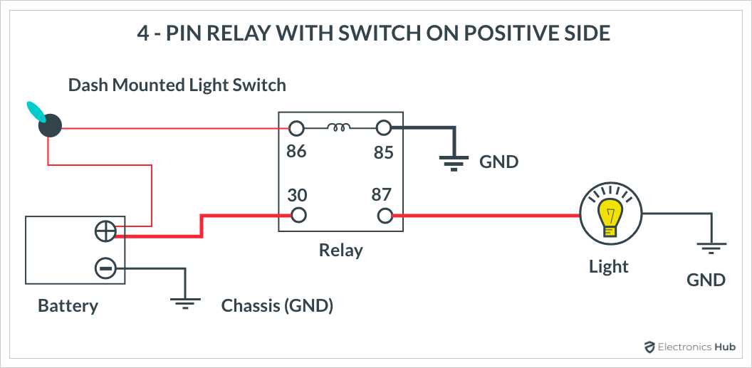
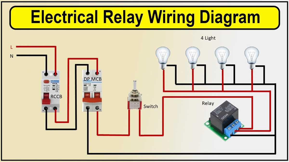
One of the common uses of five pin relays is in automotive systems. They are often used to control various components such as headlights, horns, fuel pumps, and cooling fans. For example, when the headlight switch is turned on, the relay will activate, allowing power to flow to the headlights. This helps to protect the headlight switch from excessive current and prolong its lifespan.
In industrial settings, five pin relays are used in control panels and automation systems. They can be used to control motors, pumps, valves, and other electrical devices. For instance, a five pin relay can be used to activate a motor that drives a conveyor belt, allowing efficient movement of materials in a factory or warehouse.
Another common application for five pin relays is in home automation systems. These relays can be used to control lighting, heating, ventilation, and air conditioning (HVAC) systems, as well as security systems. For example, a five pin relay can be used to turn on and off the lights in a room based on a motion sensor or a timer, providing convenience and energy savings.
Overall, five pin relays are versatile components that find applications in automotive, industrial, and home automation systems. They play a crucial role in controlling the flow of electrical current and ensuring the efficient operation of various electrical devices and systems.
Troubleshooting and Diagnosing Issues with Five Pin Relays
Five pin relays are commonly used in electrical circuits to control various devices or systems. They are versatile and can be found in automotive, industrial, and residential applications. However, like any electrical component, five pin relays can experience issues that require troubleshooting and diagnosis.
One common issue with five pin relays is improper wiring. If the relay is not wired correctly, it may not function as intended or not function at all. It is essential to consult the relay’s wiring diagram to ensure the correct connections. Check if the power supply, load, and control wires are properly connected and securely fastened. Using a multimeter can help determine if there are any breaks or shorts in the wiring.
If the wiring is correct, but the relay is still not working, the next step is to check the control signal. The control signal, usually provided by a switch or electronic circuit, activates the relay. Ensure that the control signal is reaching the relay terminals and is within the specified voltage range. If the control signal is too weak or absent, the relay may not activate. In such cases, checking the control signal source and its connections is necessary.
Another potential issue with five pin relays is damage to the contacts or coil. Over time, the contacts may become worn or pitted, hindering proper electrical connectivity. Using a multimeter to measure the resistance across the contacts can help determine if they are functioning correctly. If the resistance is significantly higher than expected or infinite, it may indicate a faulty contact. Similarly, testing the coil’s resistance can identify any issues with the coil, such as an open or short circuit.
Lastly, it is essential to consider the load being controlled by the relay. If the load exceeds the relay’s rated capacity, it can cause the relay to malfunction or fail. Check the relay’s specification sheet to ensure it can handle the load’s voltage and current requirements. If the load is within the relay’s capacity and all other troubleshooting steps have been performed, it may be necessary to replace the relay with a new one.
In conclusion, troubleshooting and diagnosing issues with five pin relays involve checking the wiring, control signal, contacts, coil, and load requirements. Following the wiring diagram, ensuring proper connections, and using appropriate testing tools like a multimeter are crucial. By methodically addressing these potential issues, it is possible to identify and resolve problems with five pin relays.
Tips and Recommendations for Installing a Five Pin Relay
Installing a five pin relay can be a straightforward process, but it is essential to follow proper guidelines to ensure proper functionality and safety. Here are some tips and recommendations to consider:
- Choose the right relay: There are various types and models of five pin relays available in the market. Make sure to choose the one that meets your specific requirements in terms of voltage, current rating, and switching capability.
- Read the manufacturer’s instructions: Before proceeding with the installation, carefully read and understand the instructions provided by the relay manufacturer. This will help you familiarize yourself with the relay’s specific wiring and connections.
- Use appropriate wiring: Ensure that you use the correct gauge and type of wiring for the relay installation. Using undersized or incorrect wiring can lead to voltage drops, overheating, and potential failure of the relay.
- Properly secure the relay: Ensure that the relay is securely mounted in a suitable location, away from excessive heat and vibrations. This will help prevent damage and ensure reliability.
- Pay attention to polarity: Check the polarity of the power source and the relay’s terminals before making any connections. Reversing the polarity can cause the relay to work improperly or not work at all.
- Test before finalizing: Before completing the installation, it is recommended to perform a thorough testing of the relay’s functionality. This includes checking for proper switching, voltage regulation, and any potential issues.
By following these tips and recommendations, you can ensure a successful installation of a five pin relay. Remember to prioritize safety and consult a professional if you are unsure about any aspect of the installation process.