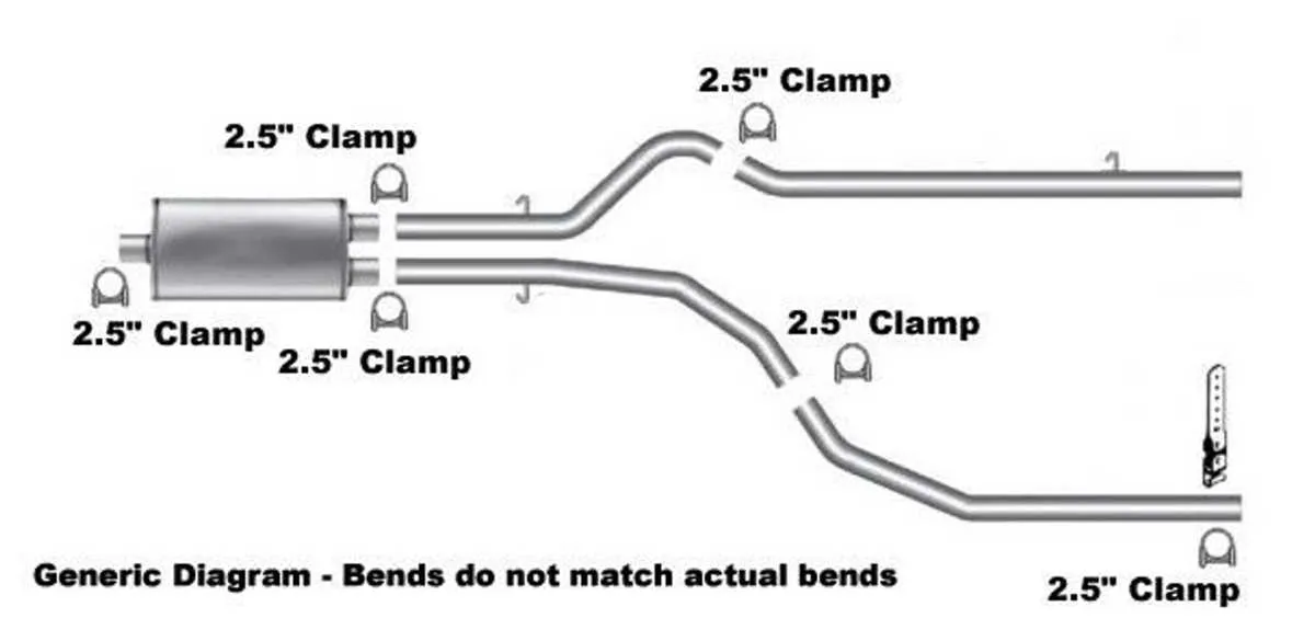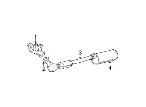
To effectively maintain or upgrade the tailpipe assembly of this popular full-size truck, it is essential to understand the exact placement and connections of its parts. The setup includes the manifold, catalytic converter, mid-pipe sections, muffler, and tailpipe, all arranged to optimize gas flow and noise reduction.
Precise mapping of the pipeline routing ensures accurate identification of components such as the oxygen sensors, resonators, and clamps, which are critical for performance tuning or troubleshooting leaks and blockages. Familiarity with this configuration supports correct part replacement and prevents costly installation errors.
Visual guides detailing each segment’s position also facilitate diagnostic work, allowing mechanics and enthusiasts to pinpoint potential faults in emission control and sound management. Knowing how these elements interconnect reduces downtime and improves efficiency in repairs or modifications.
Detailed Layout of the Emission and Muffler Components
For accurate identification of the tailpipe arrangement and catalytic converter placement in this pickup model, refer to the specific schematic illustrating the flow path from the manifold to the muffler tip. The illustration highlights key parts such as the manifold collectors, mid-pipes, resonators, and the final muffling unit.
Recommended inspection points: examine the joint connections between the header pipes and the catalytic converters to detect leaks or corrosion early. Ensure oxygen sensors are properly located before and after the catalytic units for optimal engine management.
Note on variants: configurations may differ depending on the engine displacement and year of manufacture, affecting the shape and routing of the piping and positioning of the mufflers. Always verify against the exact model year schematic for precise component layout.
Use the layout to guide maintenance, replacement, or upgrades, focusing on the flow direction indicated and ensuring clamps, hangers, and heat shields are correctly aligned for noise reduction and emission control.
Identifying Key Components in the Truck’s Emission Layout

Start by locating the manifold directly attached to the engine block; this collects gases from each cylinder. Follow the piping downstream to the catalytic converter, which reduces harmful emissions through chemical reactions. Next, identify the resonator, designed to minimize sound frequency before the gases reach the muffler. The muffler itself is crucial for dampening noise and is typically positioned near the rear axle. Tailpipes extend from the muffler to the vehicle’s rear, directing gases safely away. Pay attention to oxygen sensors placed before and after the catalytic device; these monitor gas composition and help adjust fuel mixtures for optimal performance.
Note the presence of heat shields protecting surrounding components from excessive temperatures along the routing. Flexible joints or couplings accommodate engine movement and reduce stress on the piping. Each segment is usually connected via clamps or welded joints, affecting maintenance ease. Proper identification of these parts ensures accurate troubleshooting and efficient upgrades or replacements within the truck’s emission layout.
Step-by-Step Guide to Reading the Emission Layout for Troubleshooting
Start by locating the manifold section on the schematic, as it is the primary point where gases exit the engine. Identify sensor placements, such as oxygen sensors, since their position affects data interpretation and fault detection.
Trace the path from the manifold through the catalytic converter, noting any branching pipes or resonators indicated. Pay attention to components labeled with flow direction arrows to ensure correct orientation during inspection.
Verify the presence and routing of mufflers and tailpipe sections, as blockages or damage here often cause noise and performance issues. Cross-reference any valves or bypass units shown on the chart, since they regulate flow and emissions control.
Check connection points and joint types highlighted on the layout, focusing on welds, clamps, and gasket locations where leaks commonly occur. Use the schematic’s part numbers or codes to match components for replacements or repairs.
Review heat shields and brackets depicted, as missing or loose mounts can lead to rattling or overheating problems. Follow the entire sequence of the gas evacuation route to identify possible restrictions or breaks impacting efficiency.
How to Locate and Replace Faulty Components Using the Emission Layout Guide
Begin by identifying the exact part causing performance issues through the layout schematic of the vehicle’s gas discharge pathway. Follow these steps for efficient diagnosis and replacement:
- Pinpoint the malfunction: Use the map of pipes and chambers to trace symptoms like unusual noise, decreased fuel efficiency, or emission failures to specific sections such as the manifold, catalytic converter, or muffler.
- Visual inspection: Examine the indicated parts for cracks, corrosion, or disconnections as shown in the schematic. Pay special attention to joints, clamps, and flexible connectors where leaks often occur.
- Use a smoke test: Introduce smoke into the pathway at the inlet indicated on the layout to detect leaks by watching for escaping smoke along the pipeline.
- Component removal: Refer to the schematic for the exact order of disassembly. Begin from the front manifold, moving downstream to sensors and tailpipe sections, ensuring bolts and hangers are carefully loosened.
- Replacement guidance: Match each faulty part to its labeled position on the layout. Replace gaskets and seals concurrently to prevent leaks. Follow torque specifications for bolts given in the service guide corresponding to the layout.
- Reassembly check: After installation, cross-verify with the schematic that all parts align correctly without gaps or misfits. Confirm hanger positioning for proper vibration absorption.
- Post-replacement test: Start the engine and listen for abnormal sounds. Monitor emissions if equipment is available to ensure restoration of proper function.
Using the emission layout guide as a step-by-step reference guarantees accurate localization and efficient replacement of problematic parts, reducing trial and error during repairs.