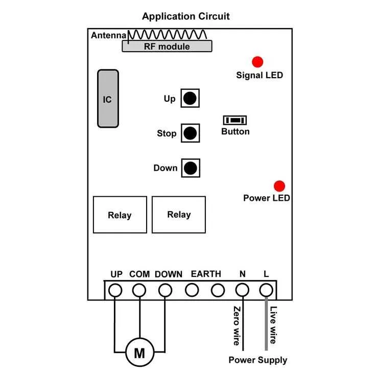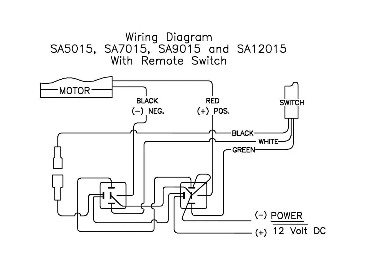
For efficient connection of a cordless hoist controller, focus on proper signal transmission and power supply integration. Use a dedicated receiver module matched to your handheld transmitter frequency to ensure reliable command execution without interference.
Essential wiring involves linking the receiver outputs directly to the actuator control terminals while maintaining a clean separation from power lines to prevent noise and signal disruption. Incorporate a secure 12V or 24V DC power source with adequate current rating based on your motor specifications.
Shielded cables and correct grounding practices enhance signal integrity, reducing the chance of operational failure. Confirm that control switches respond accurately by testing continuity and voltage levels at each connection point before final assembly.
Control System Connection Layout
Start by identifying the receiver module’s input terminals. Connect the power supply lines directly to a 12V DC source with a dedicated fuse rated at 10A. Ensure polarity is correct to avoid damage.
Use a shielded cable for signal lines to minimize interference. Connect the output leads from the transmitter control unit to the receiver’s input ports, matching each function channel precisely.
Grounding is critical: link all ground points to a common chassis ground to prevent signal noise and potential malfunction. Confirm that the control board’s relay outputs align with the device’s motor control input terminals.
For safety, integrate a manual override switch parallel to the control module, enabling direct operation in case of communication failure.
Double-check connections with a multimeter before powering on. Test each control command individually, ensuring that the actuator responds without delay or erratic behavior.
Step-by-Step Guide to Connecting the Receiver Module to the Motor Unit
- Disconnect the power source from the motor controller to avoid short circuits or damage during installation.
- Locate the control box and open its housing to access the terminal block for signal connections.
- Identify the receiver module’s output leads: typically labeled as positive (+), negative (-), and signal (S).
- Match the receiver output to the motor controller inputs, ensuring polarity aligns correctly to prevent damage:
- Connect the positive lead to the controller’s power input terminal.
- Attach the negative lead to the common ground terminal.
- Link the signal wire to the command input terminal responsible for motor activation.
Following these steps precisely will guarantee a solid connection between the receiver and motor unit, enabling smooth remote operation without signal disruption or power faults.
Choosing and Wiring the Power Source for a Remote System

Ensure the power source you select is compatible with the voltage and current requirements of the control unit. Most systems operate on 12V DC, but always verify the specifications for your particular setup. A battery is the most common power source, but ensure its capacity is sufficient for the duration of use. For instance, a 12V sealed lead-acid or lithium-ion battery can provide reliable performance, but check the amp-hour rating to match the usage demands.
Wiring the Power to the Controller requires attention to detail to prevent power loss or malfunction. Use proper gauge wire for the current draw; typically, 14 or 16 AWG is suitable for most systems. Install an appropriate fuse or circuit breaker close to the power source to protect the wiring and prevent potential damage. For longer runs, ensure you account for voltage drop and consider upgrading to thicker wire if necessary.
Connection Tips: Secure the connections to minimize resistance and ensure a steady flow of electricity. Apply dielectric grease to terminals to prevent corrosion, especially in outdoor environments. Always double-check polarity before connecting to avoid damage to the system. If your setup includes a switch, choose one rated for the correct voltage and current, and mount it in a location easily accessible for maintenance.
Common Troubleshooting Tips for Wireless Winch Remote Wiring Issues
If your lifting device isn’t responding, the first step is to check the power supply. Ensure that both the receiver and transmitter are properly powered and that there are no loose connections in the battery compartment. A weak or dead battery is one of the most frequent causes of malfunction.
Next, verify that the connection pins are correctly aligned. Misaligned pins can cause intermittent or no signal transmission. Inspect the cables for any visible damage, fraying, or corrosion. These physical issues often disrupt the flow of power or signal.
Ensure that the signal transmission distance is within the specified range. Interference from other electronic devices can also weaken the signal, so try operating the system in a different environment to rule out interference.
Check the transmitter’s switches and buttons for proper functionality. Stuck or unresponsive buttons can prevent the signal from being sent. If necessary, clean or replace the buttons to ensure they move freely.
If the unit has an indicator light, observe it during operation. A blinking or constantly lit light often indicates a malfunction, which can help pinpoint the issue. Refer to the unit’s manual for troubleshooting codes related to the indicator light.
Lastly, reset the system if the above steps don’t resolve the issue. A full reset can clear any software glitches or configuration errors that may be causing communication problems between the components.