For optimal performance of your lawn care equipment, identifying and understanding its core components is essential. Whether you’re performing routine maintenance or addressing a specific issue, knowing how the different parts interact can help prevent costly repairs and downtime. When troubleshooting or upgrading, refer to a detailed schematic that illustrates the connections and positions of key elements in the system.
First and foremost, familiarize yourself with the main mechanical units, including the cutting deck, engine assembly, and drive system. These areas are critical for ensuring smooth operation, particularly when dealing with wear-and-tear parts like belts, pulleys, and blades. A thorough examination of these sections can reveal signs of wear that might need immediate attention.
In addition to regular inspections, keep an eye on the electrical components such as the battery and wiring system. Faulty wiring or battery issues can cause performance lags or complete failure. Also, check the fuel lines and filters for any signs of clogging or leaks, which can lead to reduced engine efficiency.
Having access to an accurate layout of the machinery will simplify part replacements and ensure the correct parts are ordered, streamlining repairs. Accurate part identification is crucial, as it ensures that every component fits correctly, preventing misalignments and further damage.
Essential Components Breakdown
Ensure correct identification of each key component for easy maintenance and repairs. Begin by carefully reviewing the layout and components that influence both functionality and safety. Components such as the engine drive system and transmission assembly are critical to operational efficiency. Ensure all fasteners are properly secured to avoid any operational failures.
The deck assembly is integral for optimal cutting performance. Pay attention to the blades, ensuring they are sharp and free of any debris. Regularly inspect the spindle bearings to maintain smooth movement. If any signs of wear are evident, replacing them promptly is essential for performance.
Check the steering linkage for any looseness. A smooth steering mechanism is vital for precision handling. Tighten any loose joints and replace worn-out components, such as the steering shaft or tie rods, to prevent uneven movement or sudden malfunctions.
Fuel and electrical systems also require periodic inspection. Ensure the fuel lines are intact and free of cracks or leaks. The electrical connections should be corrosion-free, especially the terminals and wiring related to ignition. Failure to maintain these components can result in starting issues or electrical failures during use.
Finally, always refer to the maintenance schedule for specific timelines to replace wear-and-tear parts. Consistent upkeep not only prolongs the life of the equipment but also ensures it operates efficiently, with minimal downtime.
Identifying Key Components in the Z425 Assembly Layout
Start by locating the engine and its mounting bracket, which is essential for proper function. The drive system components, such as the transmission, should be identified next, as they are critical for power transfer and movement.
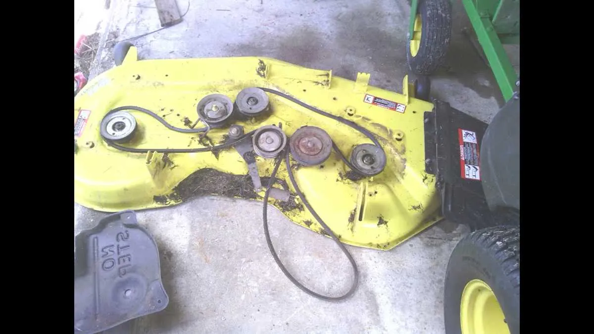
The mower deck, including the blade assembly and spindles, must be clearly marked to ensure correct alignment during maintenance or repair. Pay close attention to the belt routing, as this controls the mower’s cutting mechanism and should follow the exact path shown in the layout.
Another key area is the steering mechanism. Locate the control arms, bearings, and linkages involved in directing the movement. These parts wear over time and require periodic inspection to maintain responsive handling.
Lastly, focus on the fuel system components, such as the tank, fuel lines, and carburetor, which are essential for efficient engine operation. Ensure all connectors are tightly fitted and free from leaks.
How to Interpret the Z425 Parts Diagram for Maintenance

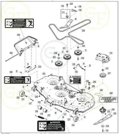
Start by identifying key components, such as the engine, transmission, and blade assembly. Pay attention to part numbers and their placement relative to each other, as this will guide you in understanding how they interact. Each section is typically organized in clusters–look for a legend or reference key to match numbers with specific parts.
Engine components are usually found at the top of the layout. Look for the fuel system and cooling components; these often require frequent checks. The transmission assembly is usually located beneath, marked with identifiers for gears and pulleys that are critical for motion.
Blade assembly parts are typically displayed in the lower part of the diagram. Here, focus on parts like the spindle, bearings, and deck mounting hardware. Regular inspection of these parts will prevent unnecessary wear and ensure smooth operation during use.
Ensure you understand the numbering system. Numbers typically reflect the order of assembly, and matching them with a detailed list of components will help you spot missing or damaged parts quickly.
For better maintenance efficiency, identify fasteners and mounting hardware. These are often indicated with a different symbol to help you recognize their specific placement without confusion. Replacing worn-out bolts or adjusting them as shown can improve overall system stability.
Common Repair Components and Their Locations

To ensure smooth maintenance, here are the primary replacement components and their typical locations:
- Blade Assembly: Positioned beneath the cutting deck, easily accessible for sharpening or replacement.
- Drive Belt: Runs between the engine and the transmission system, often located behind the deck casing for quick adjustments.
- Fuel Filter: Typically situated along the fuel line, close to the engine, for easy access during replacement.
- Spindle Assembly: Found at each corner of the cutting deck, critical for rotation and cutting performance.
- Battery: Located under the seat or on the side compartment for quick removal and maintenance.
- Air Filter: Positioned near the engine intake, accessible for regular cleaning or replacement to maintain engine efficiency.
- Spark Plug: Installed near the engine block, requires occasional cleaning or replacement to ensure smooth ignition.
- Hydraulic Hoses: Run along the frame, connecting the hydraulic pump and the lift system, typically located on both sides of the unit.
Inspecting these components regularly will improve the machine’s longevity and ensure optimal performance during operation.